
Part 2: Pellet boiler meets modern hydronics
Part two of the modern hydronics series.
RENEWABLE HEATING DESIGN || By John Siegenthaler, P.E.
RENEWABLE HEATING DESIGN
|| By John Siegenthaler, P.E.
RENEWABLE HEATING DESIGN || By John Siegenthaler, P.E.
Last month, we looked at a piping approach for adding a pellet boiler and panel radiators to an existing two-zone baseboard system. The system’s original oil-fired boiler was being retained as an auxiliary heat source. Figure 1 shows a schematic for the system.
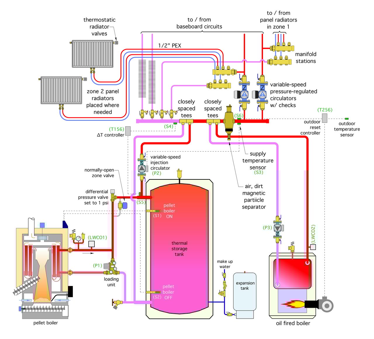
Figure 1
ENLARGE
The control objective is to maintain a target supply water temperature at sensor (S3) whenever there is a call for heat from either zone thermostat. The temperature has to be sufficient to maintain comfort in the building. It is typically based on outdoor reset control.
The preferred heat source is the pellet boiler or its thermal storage tank. Heat from this source is “injected” into the distribution system by a variable speed circulator (P2), which varies speed in response to the supply water temperature at sensor (S3). If the preferred heat source cannot maintain an adequate temperature at sensor (S3), the auxiliary boiler and its associated circulator (P3) would be operated to inject heat into the distribution system.
One control option is the “one or the other” approach. All heat for the distribution system would come from the pellet boiler/thermal storage tank or it would come from the auxiliary boiler. It would not be possible to simultaneously provide heat from both heat sources.
The decision on which heat source supplies the heat would probably be based on some minimum temperature within the upper portion of the thermal storage tank. That temperature would be likely be based on the minimum supply water temperature required to maintain comfort in the building. If the temperature at the top of the tank was too low for this requirement, the injection circulator (P2) would be turned off, and the auxiliary boiler and its circulator (P3) would be turned on. This mode of heat input would continue until either the thermostat(s) are satisfied, or the temperature in the upper portion of the thermal storage tank was increased to a sufficient value by operation of the pellet boiler.
This control approach is OK, but it lacks the ability to pull the temperature in the thermal storage tank to the lowest possible value where it can no longer contribute heat to the distribution system.
How low can it go?
Keep in mind that the water temperature returning from the distribution system is several degrees cooler than the required supply water temperature.
If the temperature at the upper header of the thermal storage tank is lower than the required supply water temperature, but still slightly above the return water temperature, it’s possible for the tank to contribute more heat to the distribution system. The auxiliary boiler can then “top off” the supply water temperature. The benefit of this approach is a longer off-cycle for the pellet boiler, which will be followed by a longer on-cycle. Longer cycles increase the thermal efficiency of the pellet boiler while also reducing emissions.
Figure 2 shows a simple control circuit consisting of two off-the-shelf controllers: A differential temperature controller (T156) and an outdoor reset controller (T256).
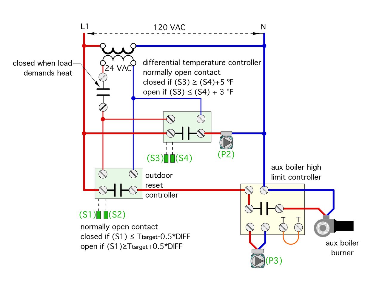
Figure 2
ENLARGE
Both controllers (T156 and T256) are powered on whenever either zone requires heat. The differential temperature controller (T156) monitors the difference between the temperature on the return side of the distribution system (sensor S4) and that at the upper header of the thermal storage tank (sensor S5). When the temperature at sensor (S5) is 5° F or more above the temperature at sensor (S4), the injection circulator (P2) is allowed to operate — at the speed determined based on its outdoor reset controller. However, if this temperature difference drops to 3° or less, the injection circulator (P2) is not permitted to operate. This allows the thermal storage tank to contribute heat to the system when possible, while also preventing heat generated by the auxiliary boiler from passing into the thermal storage tank due to the operation of circulator (P2) under conditions that don’t contribute heat to the distribution system.
The outdoor reset controller (T256) continuously monitors the supply water temperature as sensor (S6). If this temperature falls slightly below the target supply water temperature, as determined based on outdoor reset, the (T256) operates the auxiliary boiler and its circulator (P3). This ensures that a supply water temperature that can maintain comfort in the building is maintained.
Both controllers are turned off whenever all zone thermostats are satisfied. The boiler’s burner operates based on a standard high-limit controller.
Sensor sensitivity
Because the differential temperature controller (T156) is monitoring relatively small temperature differences, it’s important that both temperature sensors (S4) and (S5) are mounted using identical methods and materials. Both could be strapped to copper piping and wrapped with insulation, or both could be mounted in identical temperature wells. Do not use any mounting methods or materials that would give either sensor an accuracy advantage over the other sensor.
The combined control logic of the differential temperature controller and outdoor reset controller serves to shuttle heat from both heat sources into the system, favoring heat from the pellet boiler/thermal storage tank whenever possible, while ensuring that an adequate supply water temperature is provided to maintain building comfort. It also extends the useful life of an existing boiler as an auxiliary heat source, while minimizing the need to operate it.
The control concepts discussed can be delivered by simple, relatively inexpensive and readily available controllers. They could also be provided using software to drive a programmable controller or a building automation system (BAS) in commercial systems.
In summary, the system described in this month’s and last month’s columns brings state-of-the-art design concepts, such as variable speed pumping, outdoor reset, injection mixing, magnetic particle separation and hydraulic separation into a system make-over that allows a pellet boiler to achieve peak performance. These concepts are highly scalable for large system applications.
It’s another example of how the elegance of hydronics enhances the utility of renewable energy.
John Siegenthaler, P.E., is a consulting engineer and principal of Appropriate Designs, in Holland Patent, New York. In partnership with HeatSpring, he has developed several online courses that provide in-depth design-level training in modern hydronic systems, air-to-water heat pumps and biomass boiler systems. Additional information and resources for hydronic system design are available on Siegenthaler's website at www.hydronicpros.com.

