Wastewater combined treatment and dispersal
A reliable and compact footprint for onsite wastewater treatment (NSF/ANSI 40).
By David Lentz, P.E.
Stakeholders in the wastewater treatment systems industry are continuously developing new technologies to improve the performance of decentralized, onsite systems. Over the past 25 years, these efforts have yielded a technology known as combined treatment and dispersal, or CTD.
CTD is unique among sewage treatment technologies in that the treatment and dispersal of wastewater happens within a single, space-saving footprint. This is done by first clarifying wastewater in a septic tank, treating it to meet the requirements of the United States Environmental Protection Agency (EPA) secondary wastewater treatment standards. Then, the water is dispersed to the underlying native soil for dispersal within the CTD system.
Pending regulatory developments for CTD technology
Appendix H — Private Sewage Disposal Systems of the Uniform Plumbing Code (UPC) describes five technologies for dispersing septic tank effluent, including filter media (i.e., gravel) and pipe, seepage pits, cesspools, leaching chambers and bundled expanded polystyrene synthetic aggregate (bundled EPS) units. The 2024 UPC amendments add CTD systems as a sixth wastewater dispersal technology, expanding the design and installation alternatives available to designers, installers, regulators and manufacturers.
Under the future, amended terms of the UPC, CTD systems must comply with NSF/ANSI 40 - Residential Wastewater Treatment Systems, an American National Standards Institute (ANSI) standard for assessing performance relative to the EPA’s secondary wastewater treatment standards (per 40 CFR 133.102, 5-day carbonaceous oxygen demand <25 mg/l and total suspended solids <30 mg/l). The dispersal system planimetric area is determined using an efficiency factor of 0.70 relative to the required area for traditional gravel and pipe, reducing the required space. If the testing for the CTD NSF/ANSI 40 standard included dispersal media arranged in a bed, where individual trenches are consolidated into a single, continuous effluent dispersal area, then the UPC’s 50% area increase for bed configurations is exempted. This would conserve even more building lot space. The separation distance from the bottom of the CTD system to the groundwater table must be at least 2 feet (610 mm). CTD system operation and maintenance must also adhere to manufacturer's instructions.
What is decentralized wastewater treatment and CTD?
Decentralized wastewater treatment is an important but frequently overlooked part of the nation’s wastewater infrastructure that serves more than a quarter of the U.S. population (30 million homeowners). About one-third of all new single-family home developments are served by a septic or other decentralized treatment system. The EPA has identified onsite septic systems as a critical component of America’s wastewater infrastructure. CTD represents one of many technologies utilized in decentralized wastewater treatment systems.
Multiple CTD products are certified to the NSF/ANSI 40 standard, typically incorporating a manufactured device surrounded by coarse-grained sand, or “system sand,” conforming with the ASTM C33 standard’s gradation requirements. Upon entering the manufactured CTD device, effluent is distributed and filtered, with additional treatment in the surrounding system sand, resulting in secondary treated effluent. Figure 1 illustrates a typical CTD system, showing the manufactured product with system sand around and below it, underlain by native soil and with a vegetated ground surface. Figure 2 shows a common CTD product being installed, prior to backfilling it with system sand, final grading and vegetation. Secondary wastewater treatment and treated effluent dispersal occur within and around the manufactured CTD product and system sand, with treated water infiltrating into the underlying native soil.
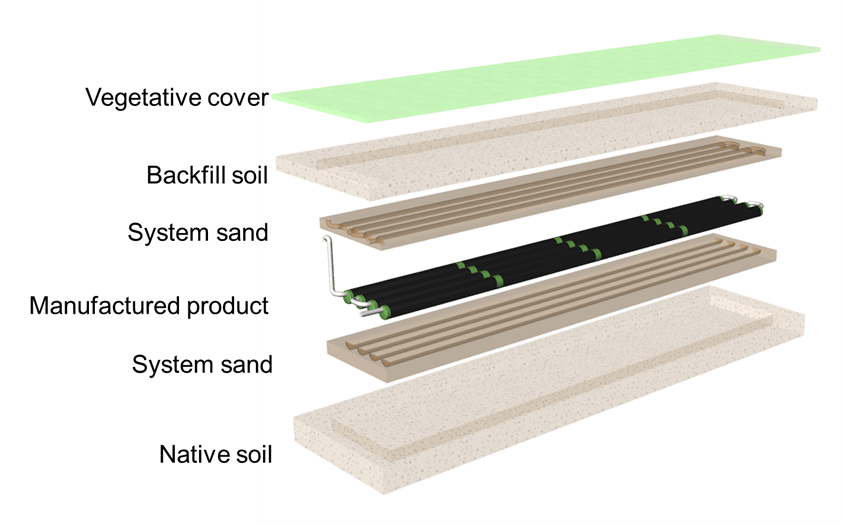
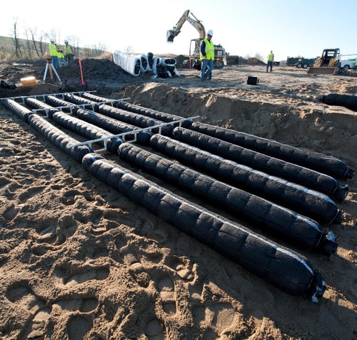
Figure 1
Figure 2
The manufactured device in a typical CTD system may include combinations of pipe, cuspated plastic, synthetic aggregate or mat material. Core components may be surrounded with filamentous plastics, synthetic aggregate and layered geo-textiles, providing surfaces capable of supporting fixed-film aerobic bacteria. Aerobic bacteria within the manufactured system and surrounding system sand biologically consumes organic compounds in sewage. The permeable system sand allows oxygen to naturally recharge from the atmosphere into the CTD components and system sand and support the microbially mediated aerobic treatment processes. System sand is also a liquid-transfer media, facilitating infiltration of secondary treated effluent to the native soil around the CTD system.
Compact footprint and installation advantages
The use of a 0.70 efficiency sizing factor to size the CTD system footprint is consistent with the UPC sizing method for leaching chambers and bundled EPS units. This accounts for the superior hydraulic flow capacity of these technologies and allows these technologies to occupy less building lot space than traditional gravel and pipe systems. An added advantage for CTD is that if the system is tested in a bed configuration under the NSF/ANSI 40 standard, the customary UPC 50% bed configuration, then the upsize requirement is exempted. This allows the system designer to consolidate multiple trenches into a single, compact wastewater dispersal footprint without having to increase the dispersal area by 50%. Using a CTD bed configuration could reduce required dispersal space by 60% compared to a traditional gravel and pipe system constructed using three-foot-wide by one-foot deep (900 mm wide by 300 mm deep) trenches on six-foot (1.8 m) centers.
The use of a two-foot (610 mm) vertical separation from the bottom of the CTD system to the groundwater table compares favorably to the five foot (1.3 m) vertical separation for a traditional gravel and pipe system dispersing untreated septic tank effluent. The two-foot (610 mm) vertical separation distance aligns with the vertical separation distance for secondary treated wastewater in the California Water Resources Control Board Onsite Wastewater Treatment Systems Policy (2012).
Operational advantages
The benefits of a zero-energy, non-mechanical system that provides NSF/ANSI 40 standard, level secondary treated effluent are significant from an operations and maintenance perspective. Without the need for an external power source, there are no concerns about aerators or recirculating pumps shutting down as would occur for an electro-mechanical system. This results in the “treatment” tank becoming a septic tank, as effluent is no longer treated. In contrast, natural, biological treatment processes in a CTD system continue to function even during a power outage.
Maintaining the electro-mechanical components in mechanical treatment systems is essential to proper function and achieving secondary wastewater treatment. For non-mechanical CTDs, there are no moving parts, so replacement parts are not required. Therefore, the need for operation and maintenance beyond that required for a traditional gravel and pipe system is virtually eliminated.
Summary
The planned addition of CTD technology to the 2024 UPC introduces the use of systems proven through the industry-recognized NSF/ANSI 40 standard to achieve secondary wastewater treatment standards. CTD has been in use across North America for over 25 years, with installations surging in the past 10 years as wastewater industry stakeholders seek reliable, sustainable, non-electric, low-impact means of treating and dispersing wastewater. CTD systems return treated water to the underground environment where groundwater resources can be recharged and are resilient to power loss, climate change and natural events such as wildfires. As a result, CTD has transitioned to be a key element of the wastewater treatment system framework in several states.
Between a space-saving design and reduced vertical separation to the groundwater table, CTD technology can be used for challenging water treatment sites that are space-constrained and/or have shallow-groundwater conditions. CTD technology is a promising tool that can provide future opportunities for innovative designs that overcome site-related design and construction challenges while delivering environmentally protective, dependable long-term service.
David Lentz, P.E., is regulatory director at Infiltrator Water Technologies, in Old Saybrook, Connecticut.