
Paying for heat
Heat metering presents a growing opportunity for hydronics professionals.
RENEWABLE HEATING DESIGN || By John Siegenthaler, P.E.
RENEWABLE HEATING DESIGN
|| By John Siegenthaler, P.E.
RENEWABLE HEATING DESIGN || By John Siegenthaler, P.E.

Apartment buildings and condominiums are home to families with different comfort preferences or attitudes on energy use. Similarly, many commercial buildings are divided into spaces where tenants have different temperature requirements or usage schedules.
In some buildings, the thermal energy required to heat or cool each adjoining space is supplied by the building owner at a fixed monthly cost, irrespective of usage. In other buildings, each space is equipped with its own heating and cooling system, along with the associated meters for electrical and natural gas usage. The cost of heating and cooling is paid directly to a utility by the owner or tenant. Those that use their systems conservatively enjoy lower bills and vice versa. It’s a “pay for what you consume” concept.
Drawbacks
Buildings where each divided space has its own self-contained mechanical system are more equitable from an energy usage standpoint, especially for spaces where thermostat settings are lower, or occupants are not using the space for extended periods (vacations, frequent travel, etc.) Still, there are several reasons why use of individual mechanical systems is not the best technical or economic option for such buildings.
One disadvantage of individual heating systems is that each building space will be assessed a monthly basic service charge for the natural gas meter.
Another drawback is a very limited selection for combustion-type heat sources intended for small spaces with low design heating loads. This often results in oversized heat sources leading short cycling, reducing service life and lowered efficiency.
Each combustion-type mechanical system also requires its own fuel supply and venting system. This requires gas distribution piping throughout the building, and several penetrations of the building envelope for combustion air and exhaust piping. If those penetrations are through the roof, the likelihood of future maintenance to prevent leaks increases.
Separate mechanical systems also take up floor or wall space within each unit. This decreases useable living space or space that would otherwise be available for commercial purposes.
Yet another drawback is access and scheduling for service. Depending on the equipment used and what has to be done, servicing may cause odors, noise, spillage, restrictions on use of space or other inconveniences.
Think different
An alternative to this business-as-usual of individual mechanical systems in each building unit is to centralize heating and cooling production and combine it with a distribution system that carries heated or chilled water to each unit.
This is not a new concept. Central heating and cooling plants have been used in many North American buildings for decades. But until recently, most of these systems lacked the ability to accurately measure the thermal energy usage of each space served by the central system. Without such measurements, it is not possible to know where the heating or cooling energy goes, and follow up with “pay for what you use” invoices.
That situation is changing in North America. Modern hardware for accurately measuring the thermal energy transferred from a central plant to each building space is now available. It’s called “heat metering,” and presents a growing opportunity for those involved with hydronic heating or cooling systems.
Heat metering, which is extensively used in Europe, requires continuous and accurate measurement of the fluid flow rate into and out of each building space, along with the temperature change of the fluid as it passes through the heat emitters (or cooling terminal units) in that space. Figure 1 shown the basic concept for how this is done using an electronic flow meter and precision temperature sensors located between a heat source and a load.
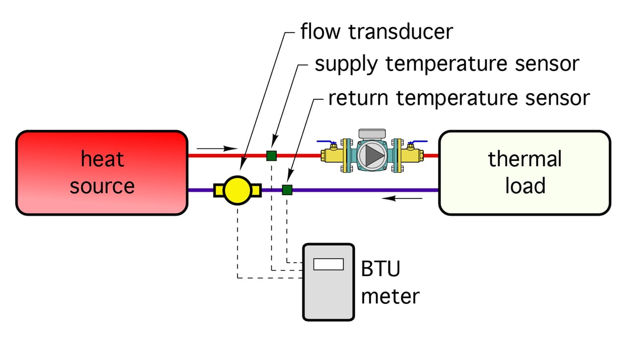
Figure 1
ENLARGE
Figure 2 shows an example of a modern heat meter suitable for use in residential or small commercial building spaces.
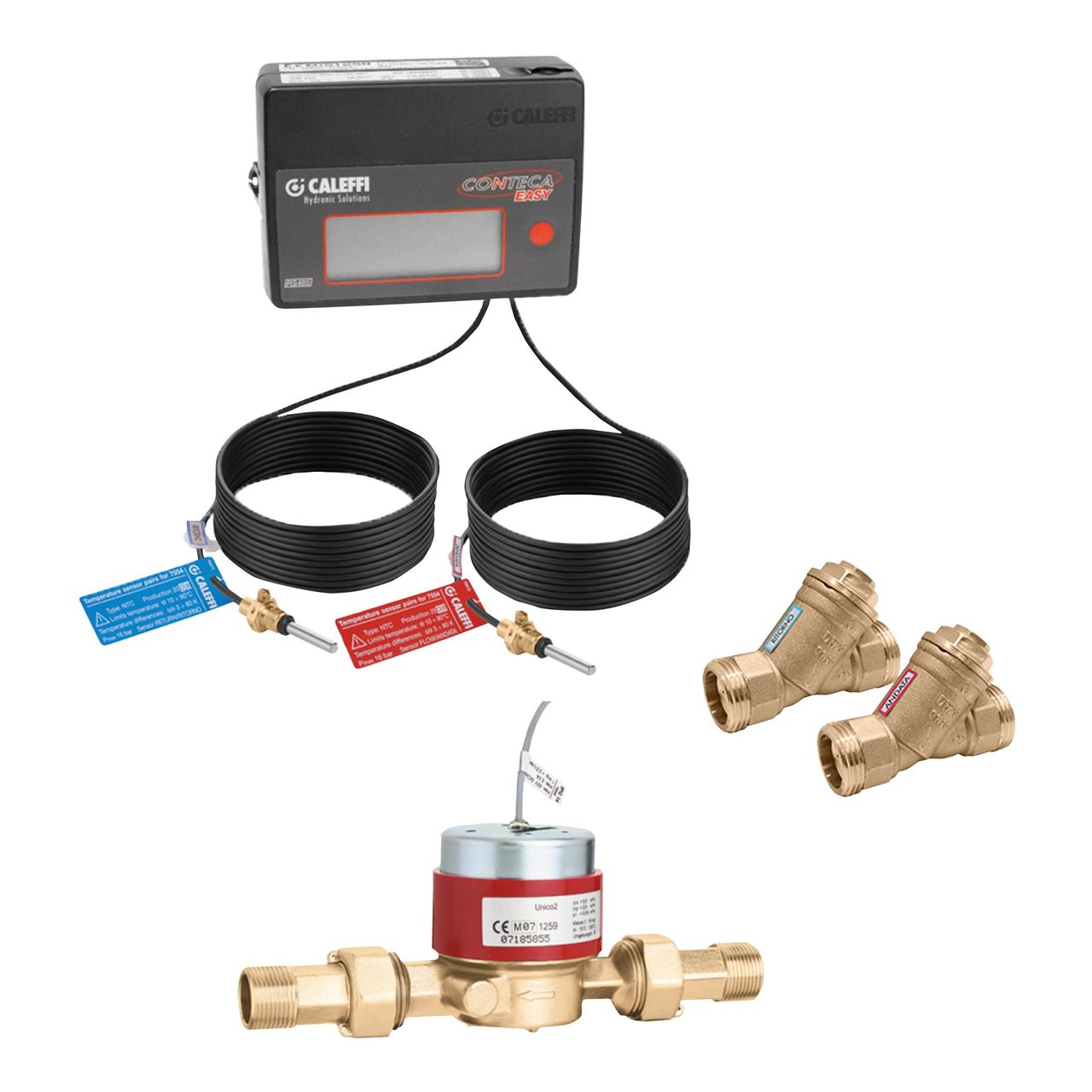
Figure 2
The electronics needed for calculating heat transfer rate and total heat transferred are contained in the heat calculator unit seen at the top of Figure 2. The two RTD temperature sensors are supplied as a matched pair, and with a cable permanently attached to both the sensor element and the terminals in the heat calculator unit. The electrical resistance of these cables is accounted for during the meter’s calibration. Because of this, these cables should never be cut, spliced or detached from the meter. Any extra length of sensor cable supplied with the meter should be neatly coiled, secured with zip ties and mounted where it will not be disturbed.
Several types of flow meters are used for heat metering, including turbine, vortex, electromagnetic and ultrasonic. They all have their advantages and limitations. In general, a heat metering system is supplied from its manufacturer as a fully matched group of components including the flow meter, temperature sensors, sensor wells, heat calculator unit and even some fine stainless steel cable with lead seals. The latter are used to discourage tampering with any hardware that could affect the meter’s reading. Once these seals are set, breaking or tampering with them could have serious legal consequences, depending on the specific agreement between the energy provider and the clients of the system.
By default, most heat meters are configured assuming that water is used as the system. The firmware in the heat calculator accurately calculates the density and specific heat of water, and uses these temperature-dependent fluid properties to maintain accurate calculations for rate of heat transfer and total heat transferred over time. When used in systems operating with glycol-based antifreeze solutions, modern heat meters can be field configured to adjust their calculations based on the specific heat and density of these fluids.
Modular approach
Heat metering is an ideal complement to a centralized multiple boiler system that provides heat for space heating and domestic hot water in multi-occupancy buildings. Hot water from the central boiler system is circulated through main piping that connects to a “heating interface unit” in each building space.
Heating interface units are available in several configurations depending on the loads they must provide. One configuration that provides space heating and domestic hot water is shown in Figure 3, along with a schematic that represents its major components.
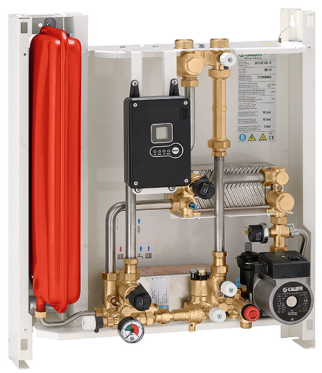
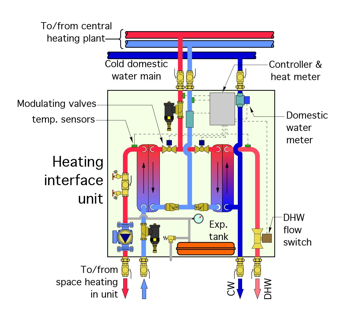
Figure 3a
Figure 3b
ENLARGE
Heating interface units are usually mounted in wall cavities within the building unit and close to the distribution pipes from the central plant. They have two connections for the heating supply and return pipes, and a third connection for cold domestic water supply.
When space heating is required, a modulating valve within the station regulates the flow of hot water from the building mains through the primary side of one brazed plate heat exchanger. This flow regulation maintains the required supply water temperature to the unit’s space heating distribution system, which is supplied from the secondary side of the heat exchanger.
A flow switch detects when there is a demand for domestic hot water. A second modulating valve then regulates the flow of hot water from the building mains through the primary side of a second brazed plate heat exchanger. This flow regulation provides the desired domestic hot water temperature exiting the secondary side of that heat exchanger.
The total space heating and domestic water heating energy used is measured based on the flow rate and temperature drop of the water from the building mains, between where it enters and leaves the heating interface unit. The controller within the heating interface unit records the total thermal energy used.
Greater outreach
Heat metering is also ideal for district heating applications, where heat (and in some cases chilled water) is supplied to each of several buildings from a central plant. Figure 4 shows the concept of such a heating system where the central heating plant consists of three staged boilers.
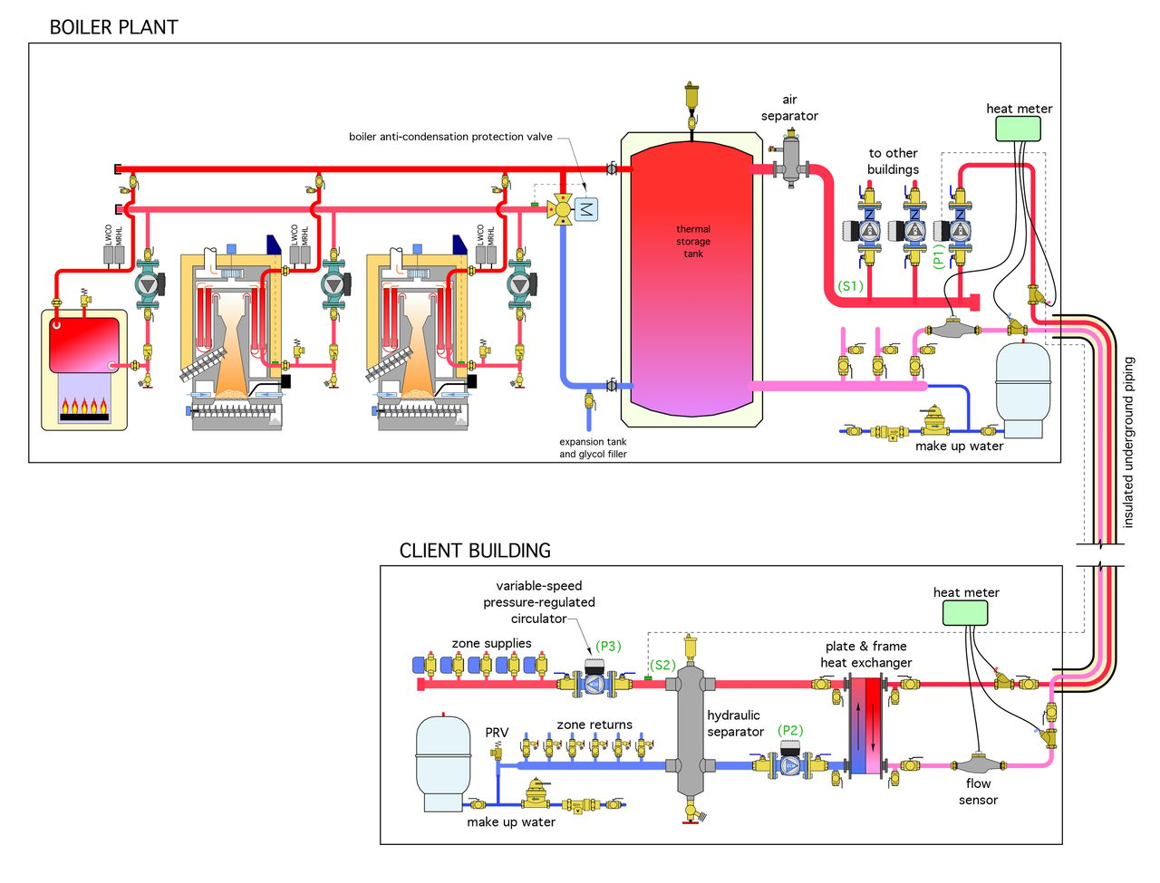
Figure 4
ENLARGE
The boilers are staged to maintain the thermal storage tank within a specific temperature range. Hot water from this tank is routed by a variable speed circulator through underground insulated piping to a plate and frame heat exchanger in each “client” building. These heat exchangers prevent any cross-flow between the central system and the distribution system within the building. Any leaks or other service issues in one building are not going to impact central heat delivery to the remaining client buildings. Auxiliary boilers may also be present in the client buildings to maintain comfort if there is a service issue with the central system.
Two heat meters are shown in Figure 4. One measures the heat leaving the boiler plant and going to one client building. The other measures the heat arriving at the client building. The difference between these meter readings would indicate the heat loss in the underground distribution piping. Although it’s nice to have such information, it is not always necessary to install two heat meters. The location of a single meter would depend on how the client buildings are billed for the heat they receive — e.g., is the billing agreement based on the heat leaving the boiler plant or the heat arriving at the client building?
Playing by the rules
In the U.S., an ASTM standard titled Standard Specification for Heat Meter Instrumentation (ASTM E3137/E3137M-17) was issued in February 2018. It covers the accuracy requirements for several categories of heat-metering equipment. This standard was developed over several years. It references several previous heat-metering standards, such as EN1434, which is extensively recognized in Europe. This new standard is expected to be frequently cited by engineers specifying heat metering systems.
Use it
Heat metering represents a significant and broad emerging market in North America. It’s a niche that’s ideally suited to those working with hydronic heating and cooling systems. It’s a technology that provides performance verification, assists in diagnosing system problems, promotes energy conservation and allows equitable sharing of energy costs. This article is but an overview of what’s possible. If you’re involved with hydronics you need to follow this developing market.
AndreyPopov/iStock/Getty Images Plus via Getty Images.
John Siegenthaler, P.E., is a consulting engineer and principal of Appropriate Designs, in Holland Patent, New York. In partnership with HeatSpring, he has developed several online courses that provide in-depth design-level training in modern hydronic systems, air-to-water heat pumps and biomass boiler systems. Additional information and resources for hydronic system design are available on Siegenthaler's website at www.hydronicpros.com.

