

Room with a view
Modern hydronics technology addresses heating challenges from the floor up or from the ceiling down.
RENEWABLE HEATING DESIGN || By John Siegenthaler, P.E.
RENEWABLE HEATING DESIGN
|| By John Siegenthaler, P.E.
RENEWABLE HEATING DESIGN || By John Siegenthaler, P.E.
Figure 1
Over the years I’ve had opportunities to work with several architects. They’re interesting people who have the ability to meld art with building technology. Sometimes the result is more “art,” and sometimes it’s more “building.” In either case, their designs typically get handed off to engineers with the simple request: Figure out how to heat my creation…
Most architects love glass and use it liberally in their designs. They may be motivated to capture a beautiful view, connect the interior with outside nature, allow sunlight in, demonstrate the concept of minimal (but adequate) vertical support or perplex HVAC engineers assigned to make the resulting structure comfortable. I admit to joking with various builders that “Most architects use just enough studs to hold up the roof, everything else is glass.”
Human aquariums
Floor-to-ceiling glass, or a wall full of multi-slider doors, looks elegant in those staged “beauty shot” photos — especially the ones taken at night with all the interior lights turned on. But heating pros usually see those facades in a different perspective. They ponder what all that glass “feels like” on a cold winter night.
Large glass surfaces are excellent radiant heat sinks on cold nights. They can significantly depress the mean radiant temperature (MRT) of interior space. They also create “radiant asymmetry” within the space. The side of your body facing the glass feels the chill, even when the surrounding air temperature is fine (e.g., typically 68-72° F).
If your into numbers, check out the free MRT calculator. It allows you to construct a detailed 3D model of a room and experiment with different surfaces to gauge their effect on mean radiant temperature.
Large glass surfaces also create significant downward air currents when it’s cold outside. The physics is simple; air in contact with the interior glass cools, becomes more dense and descends. Warmer air farther away from the glass circulates up and over to follow the cooler air. The downdraft impinges on the floor and spreads into the room, right where one of the most thermally-vulnerable parts of the body — the feet — are located. Curtains or shades that allow free airflow above and below their installed height can accentuate these downdrafts.
Pushing upward
The traditional way of dealing with downdrafts created by window walls is to install convectors at the base of the wall directly under the glass. Choices range from baseboard (common in residential systems) to pedestal-mounted convector/radiators such as shown in Figure 2 to recessed trench convectors, as depicted in Figure 3.
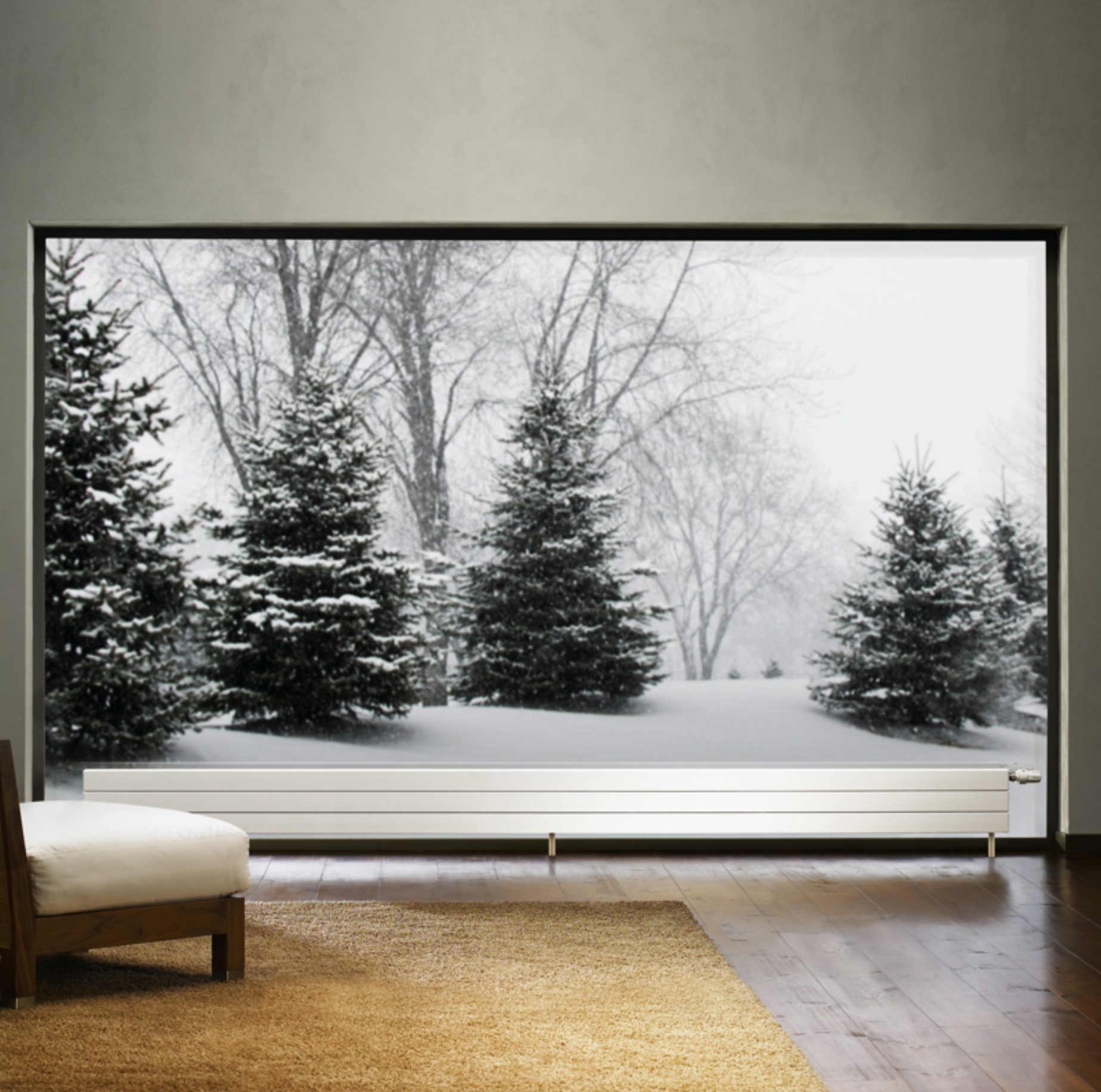
Figure 2
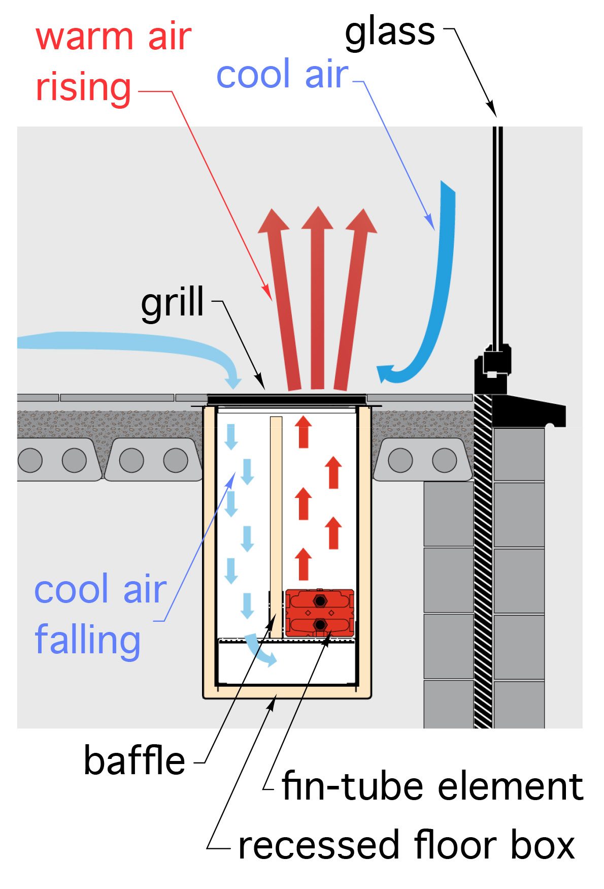
Figure 3
When there’s a nominal foot or more of wall under the glass, some type of low-profile convector, operated at a relatively high water temperature, can create adequate upward convection current to counteract the draft.
A more challenging scenario is when there’s little if any wall at the base of the glass. If the “floor-up” glass is stationary a pedestal-mounted convector (Figure 2) is possible, but it’s a visual distraction as well as a potential toe kick. Most clients who can afford glass walls won’t relish such a convector interfering with the intended architectural aesthetics.
Trench convectors are recessed into the floor deck and covered with a grill that’s flush with the finish floor surface. They can be a challenge to integrate into floor framing that’s running perpendicular to the exterior walls, or with concrete slab-on-grade floors. They also have to be periodically opened to vacuum out dust and other small objects that inevitably end up in the trench.
Shining down
Another approach that’s widely used in European buildings with expansive exterior glazing is to “shine” some radiant heat from ceiling-mounted panels on the area inside those large glass walls. This approach removes any visual or spatial interference with the floor plane under the glass.
One approach that I’ve used is to create a radiant ceiling panel using the construction shown in Figure 4.
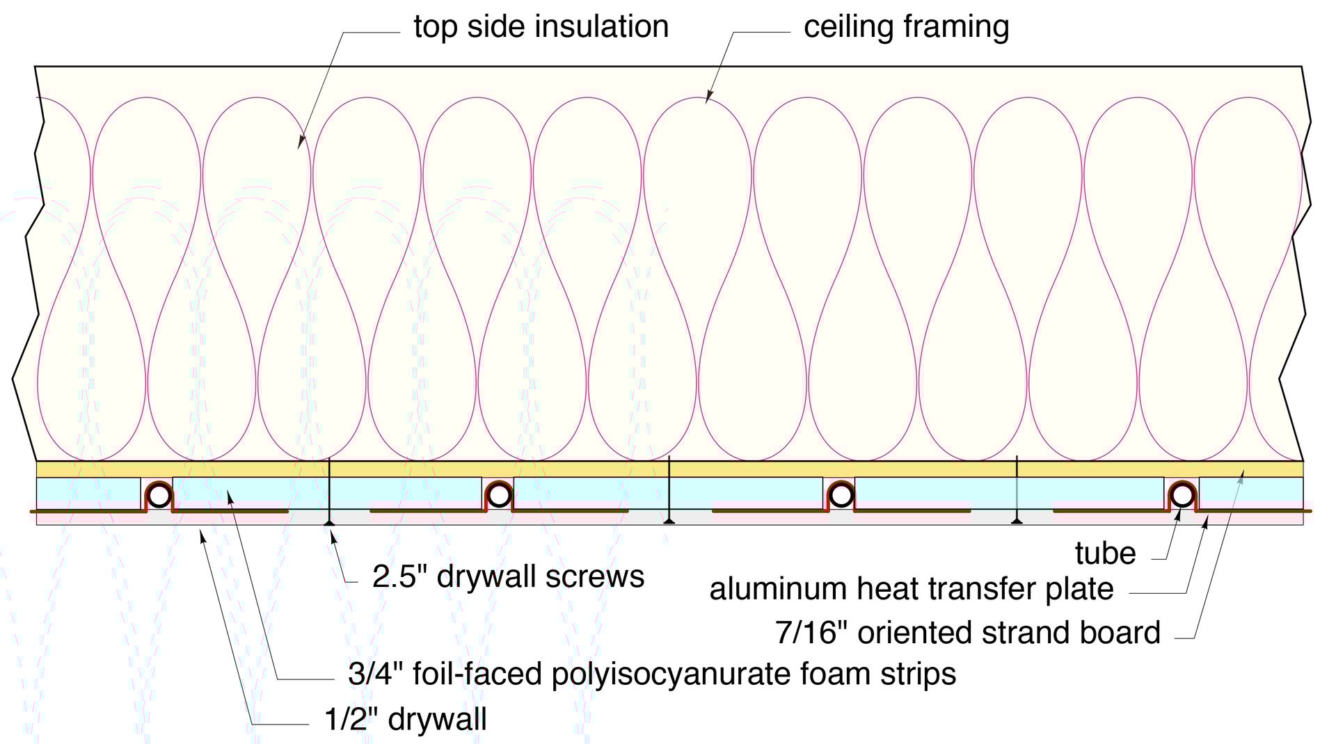
Figure 4
ENLARGE
Figure 5 shows how this construction, at a width of 4 feet, was integrated into an otherwise flat ceiling to create a “troffer” appearance.
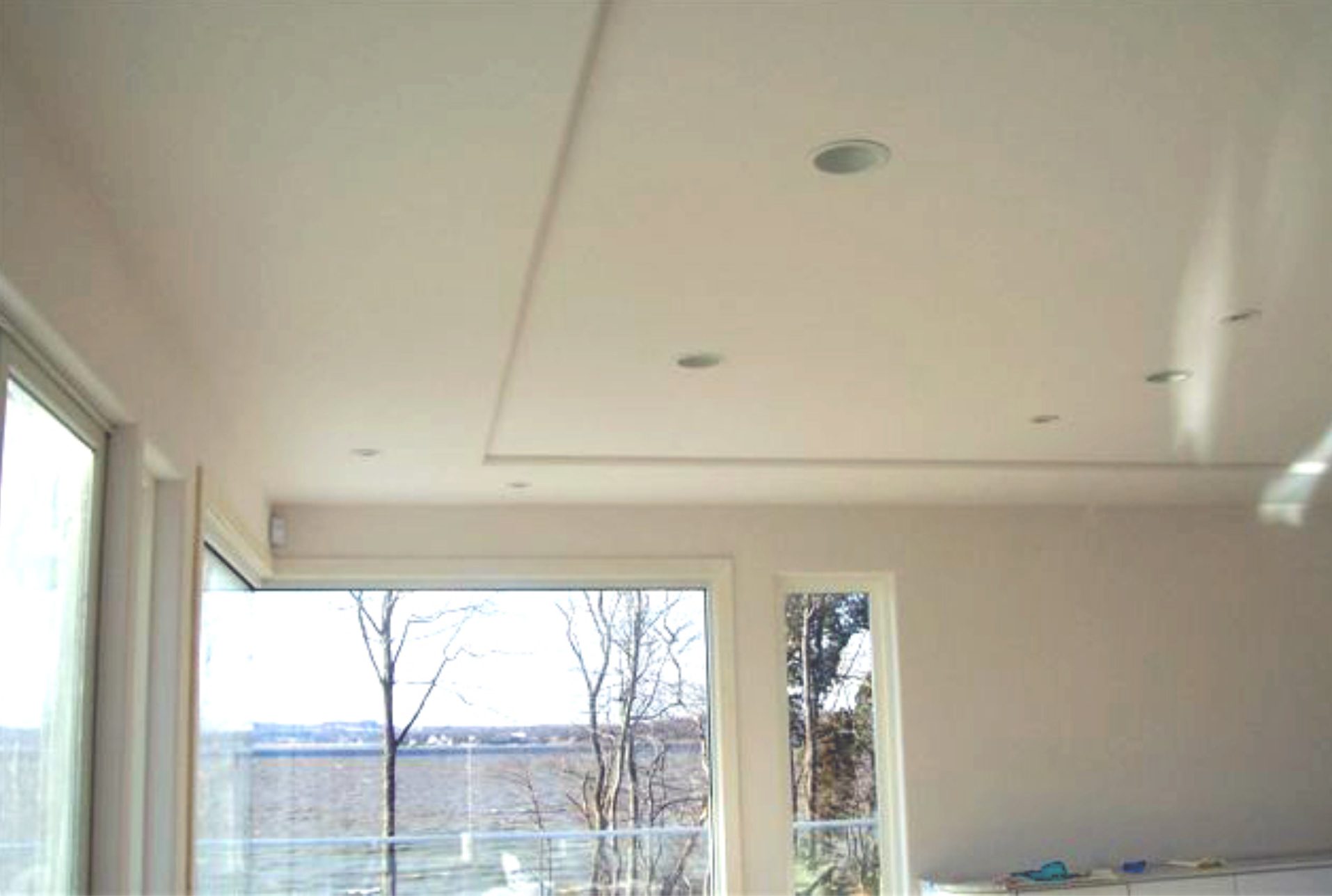
Figure 5
The building using this radiant ceiling panel has thin-slab floor heating with 6-inch tube spacing for several feet inside the window wall. Given the recommended surface temperature limits that apply to floor heating (85° F max), the floor alone would not deliver the full design heating load of the heavily-glazed space. A 2-stage thermostat was used in this project. The first stage operated the floor heating circuits and the second stage operated the radiant ceiling panel.
The heat output of a radiant ceiling panel having the construction shown in Figures 4 and 5 can be estimated using Formula 1.
Formula 1
Where:
Q = heat output (Btu/hr/ft^2)
Twa= average water temperature within panel (°F)
TR = room air temperature (°F)
A suggested upper-temperature limit for drywall is 120° F. If one assumed an average water temperature of 115° F, and a room air temperature of 70° F, the output of the radiant ceiling panel would be about 32 Btu/hr/ft2. A four-foot wide strip of this panel, as shown in Figure 4, would yield about 128 Btu/hr/linear foot.
When more is needed
There may be situations where the required heat output from the ceiling panel needs to be higher than what the temperature limit for drywall would allow. One option would be to use prefabricated radiant ceiling panels, such as shown in Figure 6.
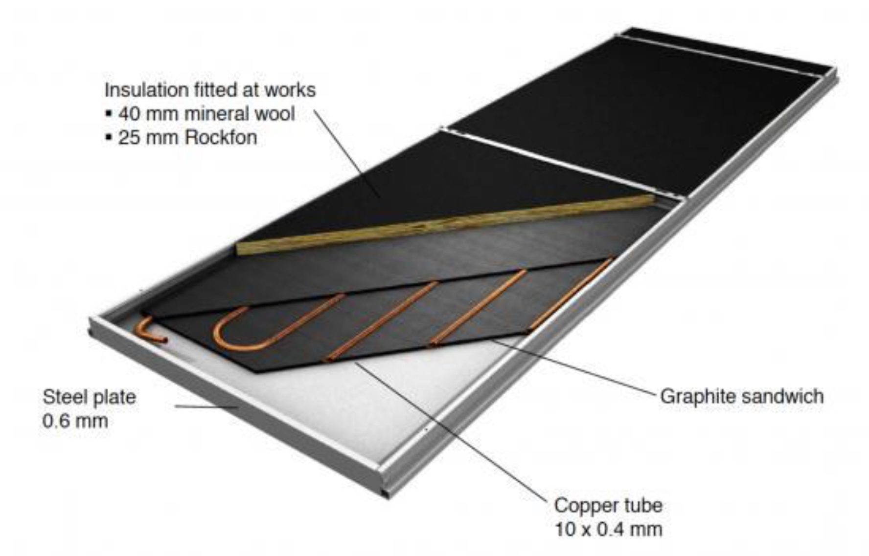
Figure 6
These panels are rated to operate with water temperatures over 200° F, if necessary. That said, such high temperatures are seldom needed in residential window wall applications. At a mean water temperature of 160° F , a two-foot wide panel releases 362 Btu/hr/linear foot. That’s a lot of “artificial sunshine” coming down to maintain comfort by those large glass walls. Most panels of this type can be flush mounted to the ceiling, (typical for residential applications), or suspended a few inches below the ceiling to create a “cloud” installation (more common in commercial applications).
Although window walls may be an “architect’s delight,” they present challenges when it comes to comfort. Modern hydronics technology provides options to address those challenges, from the floor up, or from the ceiling down.
asbe/E+ via Getty Images.
John Siegenthaler, P.E., is a consulting engineer and principal of Appropriate Designs, in Holland Patent, New York. In partnership with HeatSpring, he has developed several online courses that provide in-depth design-level training in modern hydronic systems, air-to-water heat pumps and biomass boiler systems. The fourth edition of his textbook — “Modern Hydronic Heating & Cooling” — was released in April. For more information, visit www.hydronicpros.com.
