
Three from one
Heating, cooling and DHW from a single system.
RENEWABLE HEATING DESIGN || By John Siegenthaler, P.E.
RENEWABLE HEATING DESIGN
|| By John Siegenthaler, P.E.
RENEWABLE HEATING DESIGN || By John Siegenthaler, P.E.
As global energy planning moves away from fossil fuels and toward electricity, an increasing number of hydronic heating systems are being supplied by heat pumps. Some use water-to-water heat pumps supplied by geothermal earth loops. Others use air-to-water heat pumps. Both types can supply warm water for heating, chilled water for cooling and some or all of the building’s domestic water heating load.
To buffer or not to buffer
If the heat pump with a fixed-speed compressor supplies a zoned distribution system, it is essential to use a buffer tank in both heating and cooling mode. If the heat pump has a variable speed, (e.g., “inverter”) compressor, a buffer tank may or may not be required. If the latter heat pump can reduce both its heating capacity and cooling capacity to approximately the design load of the smallest zone, or less, a buffer tank is not required. However, this scenario is the exception rather than the rule. This is especially true for highly zoned systems or systems with more heating zones than cooling zones.
One unique scenario is a system with multiple heating zones, many of which have heat output rates far less than the lowest heating capacity of the variable speed heat pump, combined with a single-zone chilled water air handler for cooling. In this scenario, a buffer tank needs to be used in heating mode but not in cooling mode.
This sets up another unique possibility where the buffer tank can buffer both the space heating zones and provide a significant percentage of the domestic water heating load.
The type of tank used for such an application is sometimes called a “reverse” indirect. The tank’s shell is filled with system fluid (e.g., water or an antifreeze solution). Domestic water passes through copper or stainless steel coils suspended within the tank shell. Several North American manufacturers now offer this type of tank. One possible system configuration using such a tank is shown in Figure 1.
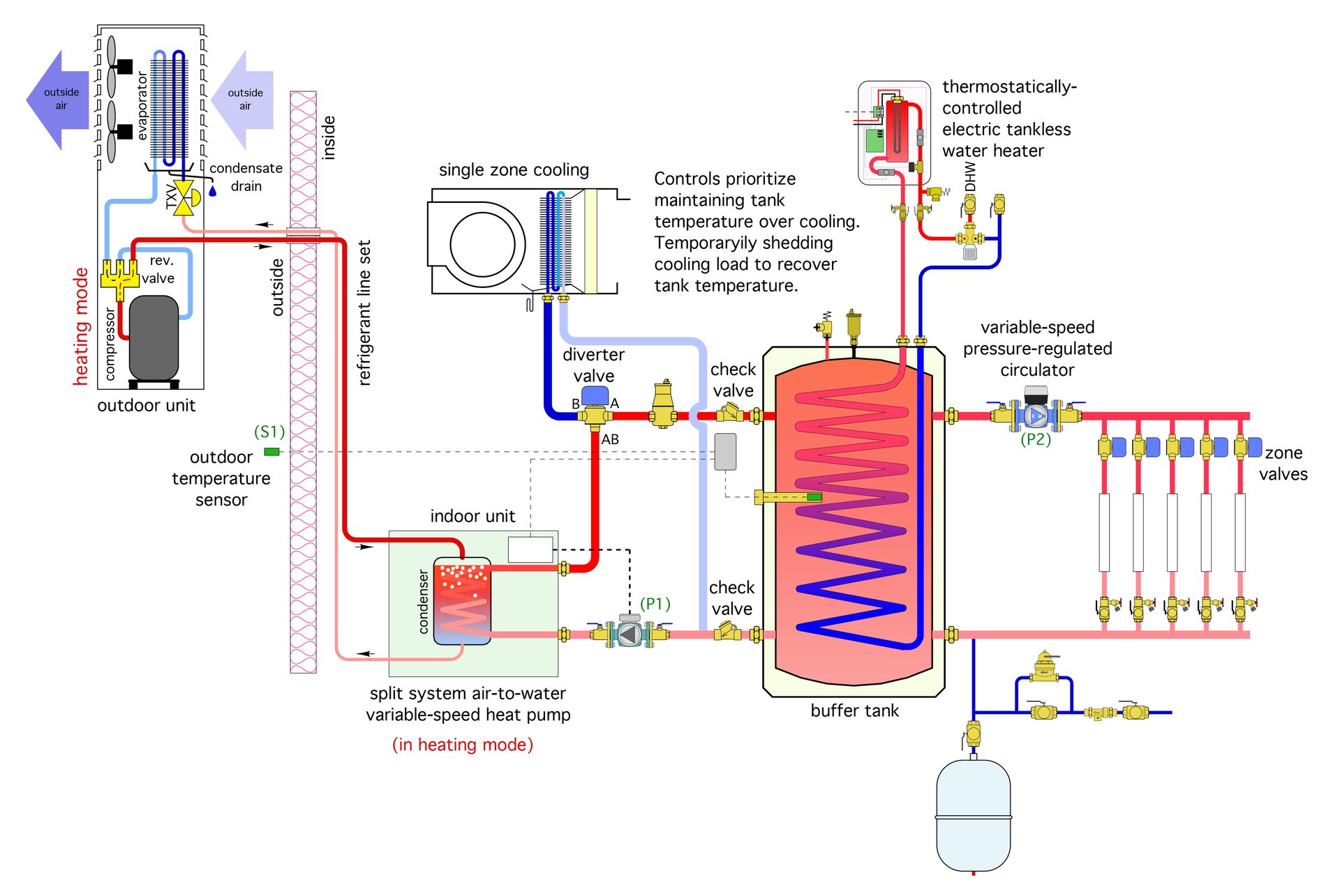
Figure 1
ENLARGE
In heating mode, the heat pump maintains the water temperature in the reverse indirect tank. This temperature might be based on a simple setpoint and differential. For example, the heat pump and its associated circulator (P1) could be turned on when the reverse indirect tank temperature sensor drops to 100° F, and off when the sensor temperature reaches 110° F. The heat pump could also be turned on and off based on outdoor reset control. The latter improves the heat pump’s COP under partial load conditions. Unfortunately, it also increases the amount of supplemental electrical energy needed to bring domestic water to a final (acceptable) delivery temperature.
Which of these control scenarios is “optimal” depends on several factors, such as the specific heating and COP performance of the heat pump, the required supply water temperature to the heat emitters, the domestic water heating load and, in the case of air to water heat pumps, the climate in which it operates. Some simulations I’ve done based on a low ambient air-to-water heat pump supplying a low-temperature hydronic system (105° F supply water at design load), located in upstate New York indicate a slightly higher seasonal COP when the reverse indirect tank temperature is based on outdoor reset rather than setpoint control. A thermostatically-controlled tankless electric water heater, such as shown in Figure 1, provides the supplemental heat needed to bring preheated DHW exiting the tank coils up to the required delivery temperature. A standard tank-type electric water heater could also be used for this final temperature boost.
Variable speed benefits
In many homes, especially those in cold climates, the design cooling load is significantly lower than the design heating load. This is where a variable speed heat pump is very helpful. It can operate at full output when necessary for design load heating, but “throttle back” on cooling capacity to prevent short cycling.
In cooling mode, the chilled water leaving the heat pump is routed to the air handler’s coil by a motorized diverter valve. It does not pass through the reverse indirect tank. The heat pump’s compressor adjusts its speed to maintain a preset chilled water supply temperature — typically in the range of 45° F to 55° F.
Mode switching
Since the reverse indirect tank is not needed for cooling operation, it can remain heated and provide most of the temperature lift required to domestic hot water production. In some cases — where DHW delivery temperature only needs to be around 120° F — the heat pump can provide all the heat required. This is especially true during “non-heating” months when outdoor temperatures are mild, or even hot. Under those conditions, the air-source heat pump will have high heating capacity as well as high COP.
When the system is operating in cooling and the temperature of the reverse indirect tank needs to be increased, the system’s controls temporarily interrupt cooling. The heat pump switches to heating mode, and the diverter valve directs flow from the heat pump to the reverse indirect tank. In just a few minutes, the temperature of the tank can be recovered, and the system can switch back to cooling. For example, a nominal 4-ton rated heat pump operating at outdoor temperatures of more than 80° F could have a heat output in the range of 60,000 Btu/h. That output could boost an 80-gallon reverse indirect tank by 10° F in about 6.6 minutes.
When switching between heating and cooling, it’s important to remember that most heat pumps have an internally-controlled minimum time delay of around three minutes between being turned off and then back on. This time allows refrigerant pressure differentials to decrease prior to restart.
Another detail that enhances comfort when switching back from heating the buffer tank to chilled water for cooling is to keep the air handler’s blower off until the coil has chilled down. The time required depends on the water volume between the heat pump and coil as well as the cooling capacity of the heat pump. In most cases, two to four minutes are all that’s required. The blower startup can be controlled by a time delay relay or equivalent BAS programming. Some air handlers contain the necessary controls for this function.
Details matter
Making this concept work smoothly requires attention to detail.
First, be sure that any piping and components that contain chilled water are insulated and vapor sealed. Don’t get sloppy here. Nature will find the imperfections in your insulation and chastise you in the form of dripping condensate. One product I really like for small scaled chilled water cooling is pre-insulated PEX tubing. When the chilled water air handler is located some distance from the mechanical room, this pre-insulated PEX can be routed through the building faster and easier than rigid tubing covered by many custom-cut and glued pieces of elastomeric foam insulation. There will also be far fewer joints and thus fewer chances of condensate issues.
Be sure to install the check valves shown in figure 1 to minimize heat migration between chilled water piping and a warm reverse indirect tank.
Finally, use a reverse indirect tank with the largest available internal coil(s). The greater the surface area of the coil, the greater the rate of heat transfer between the tank water and the domestic water in the coil(s).
Efficiency and comfort
This system concept is a great example of how modern hydronics technology can be adapted to a renewable energy heat source (e.g., the heat pump) to provide space heating, cooling, and domestic water heating loads. It’s a great fit for new energy-efficient homes, especially those intended to reach net-zero status - while maintaining the “gold standard” of comfort that no mini-split or “all air” system will ever deliver.
OgnjenO/iStock/Getty Images Plus via Getty Images.
John Siegenthaler, P.E., is a consulting engineer and principal of Appropriate Designs, in Holland Patent, New York. In partnership with HeatSpring, he has developed several online courses that provide in-depth design-level training in modern hydronic systems, air-to-water heat pumps and biomass boiler systems. The fourth edition of his textbook — “Modern Hydronic Heating & Cooling” — was released in April. For more information, visit www.hydronicpros.com.

