Oh, the lowly
grease trap
Understanding the worst places in a commercial kitchen or food processor.
By Robert DiPlacido
So, one day we did a web-search for Mike Rowe and “Dirty Jobs,” asking: Was there a show that had Mike, hands, shoulders and head deep within a big, fat grease trap? The closest we came to finding the answer is a YouTube video with Mike titled, “Episode 44, The Greaseman Cometh.” Though it was a great story — as they all are — it had nothing to do with grease traps or interceptors.
Considering all the places he’s been while slathered with sweat and slime, Mike Rowe’s never seen the least glamorous, ugliest, most unlovely places on planet Earth. Those secrets are held inside restaurant grease traps — the devices design to intercept fats, oils and grease (FOG) from leaving a kitchen facility and entering a sewer system.
Slimy FOG compounds that, by design, are trapped and held in place are chiefly byproducts of cooking that leach out of meats and dairy products. The idea is wastewater flows from sink, wash area and cleaning table drains into tanks that are designed specifically to trap the crap that shouldn’t enter sewage systems. In a grease trap, solids settle while oils, fats and grease — usually lighter that water — float to the top where they’re arrested, keeping them from flowing out with the wastewater discharge.
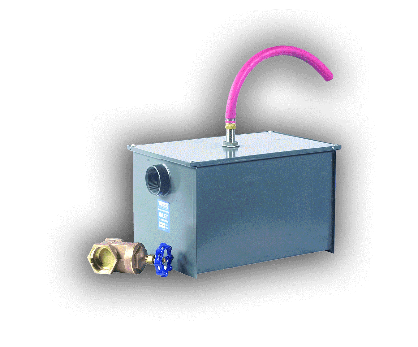
Typically, a grease interceptor works the same way as a grease trap, but on a much larger scale. They’re actually pretty simple devices, and their basic design hasn’t changed since the 1880s.
Flow rate is what defines the difference between a grease trap and a grease interceptor. A grease trap is intended for use with flow measuring less than 50 gpm. Larger operations — such as a poultry process plant — require the installation of a larger-scale “grease interceptor.”
Ask anyone in the municipal wastewater treatment business — one of the biggest environmental problems grease can have, outside of clogging pipes, is the disruption caused in the “digestive” process of water treatment plants. Bacterial processes are used to break down and clean sewage, but FOGs can destroy these bacteria, causing all sorts of problems.
High inlet/outlet layouts prevent the clogging of the inlet line, commonly seen in systems that have a lower inlet. This clogging, like that of the wastewater piping system, can result in a blockage or backup in the system or a reduction in separation percentage (grease to water) unsuitable for municipal wastewater systems;
Vertical baffle plates cause immediate disruption in the flow, forcing fluids directly to the bottom of the separation chamber, where it is then met by the direction flow plate, initiating the separation process. From there, freshly separated water is reintroduced to the main water system and the grease is cleaned out by removing the cover and skimming it off the top;
Flow controls play a key role in the proper functionally of a grease interceptor because they’re designed to work properly under certain flow conditions; and
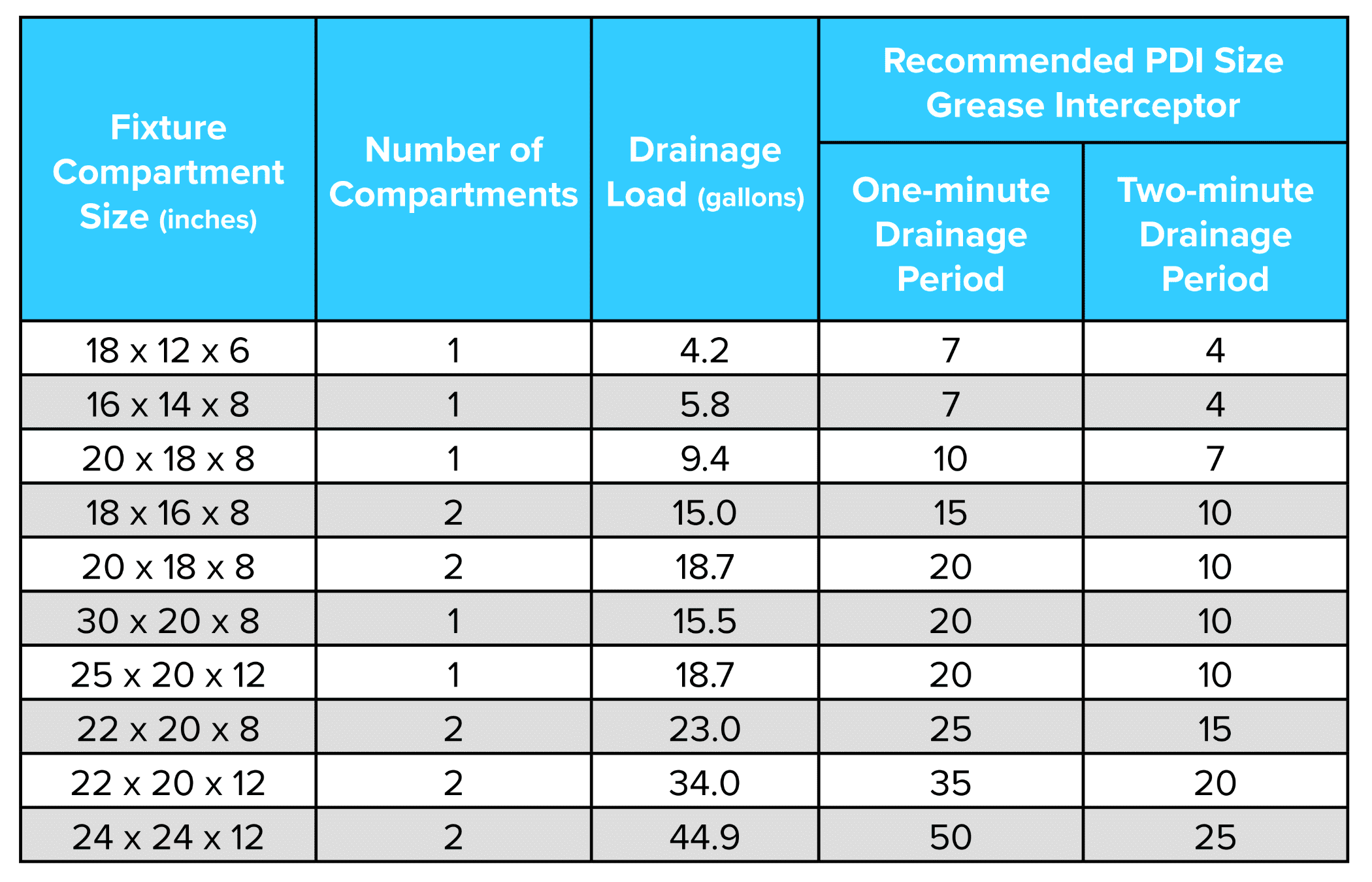
Sizing is important. Prior to installing an interceptor, check with local authorities for sizing requirements. They may differ according to specific locations.
The following will outline the most common method for grease trap/interceptor sizing along with a few variables, with solutions that may affect overall system performance.
Sizing
Performance affecting variables
In the scenario described above (with a flow rate of 55 gpm), additional flow control devices may be needed if the incoming velocity/flow exceeds the recommended velocity. A high velocity incoming flow results in more turbulence, which reduces the system’s efficiency and increases the separation time.
Interceptor size needs increase if:
The incoming ratio of grease to water increases. If the ratio of grease to water is higher, the separation process will not work; and
There’s a possibility of detergents in the system, such as soap/cleaning products, etc. Detergents break down the grease particulars into smaller particles that will not separate properly and can pass through a grease interceptor — polluting the flow of water released into municipal treatment systems.
By increasing the size of an interceptor unit, both the flow path and separation time are increased, allowing the system to capture the particles more effectively.
Install a solids interceptor in series (prior to the grease Interceptor) if:
The system contains solid particles (such as food). Because grease has a lower specific gravity than water, it floats to the top with ease. But when a solid (such as a French fry) is introduced, it sinks to the bottom, and overtime, can pass through the system. By introducing a solids interceptor prior to the grease intercepting process, this French fry or any other solids are caught and will not be at risk of re-entering the city’s drainage system.
Standard Configurations
On Floor
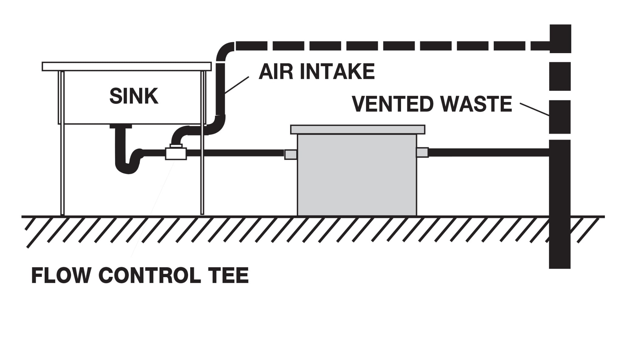
Recessed
Recessed With Extension
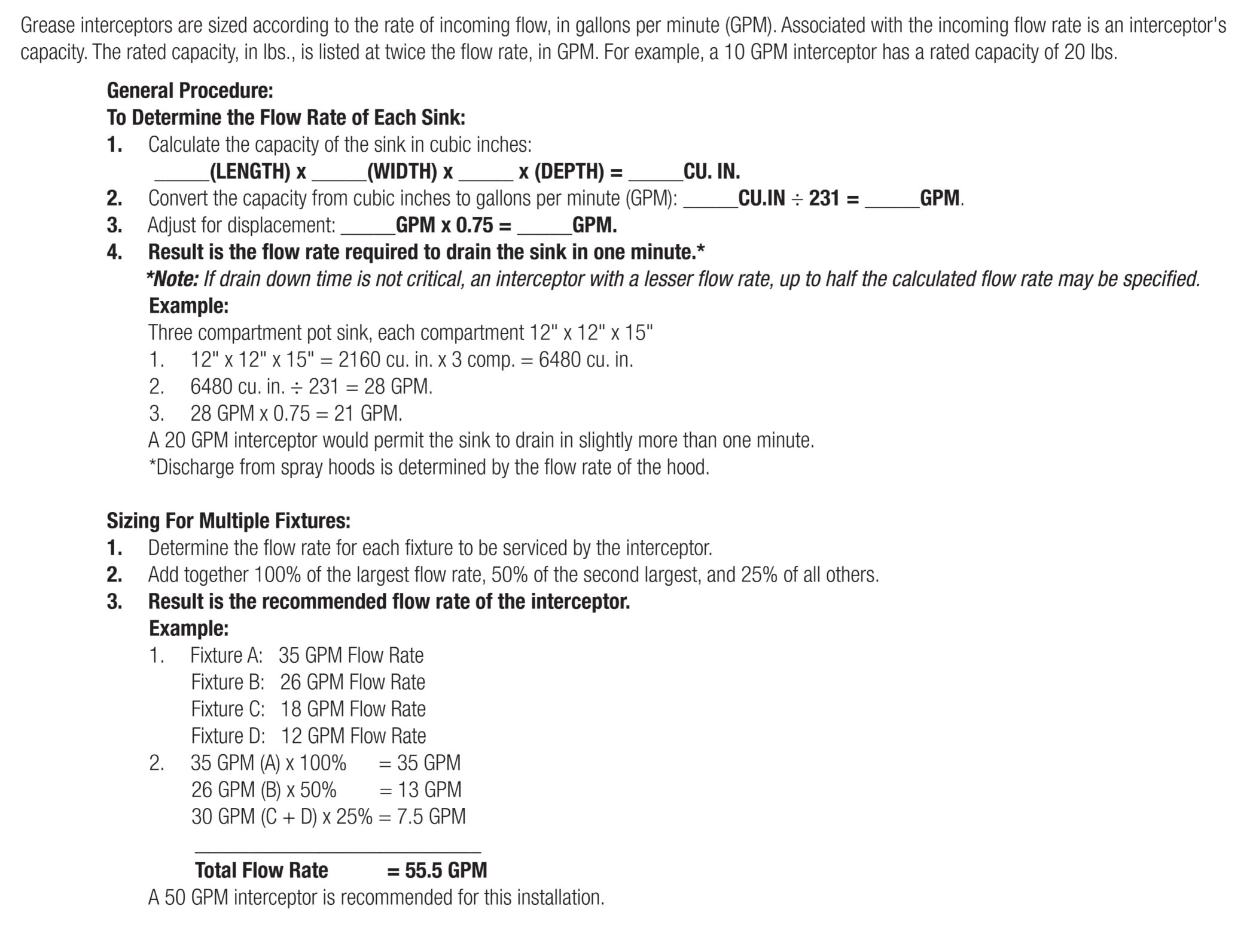
The installation of a grease interceptor is just as important in the operation of the system’s performance. First and foremost, the location of a grease interceptor should be as close as possible to the source of grease due to the cooling and solidification potential of grease over longer plumbing runs. For best results, the grease interceptor can be installed in any of the three orientations illustrated above.
Be sure — prior to finalizing the install location — to consider the clearance necessary to accommodate any connective piping and provide sufficient space for proper removal of the cover for cleaning purposes.
Key considerations
Grease interceptors are not designed to handle solid debris. In an application where solids are present, such as all sinks where garbage disposals are used, a solids interceptor is required to be used in conjunction with the grease interceptor. Due to the nature of greases — which have a natural attraction to solid particles — the presence of solids dramatically reduces a grease interceptor’s effectiveness. This can result in everything from unpleasant odors caused by the decay of solids to the clogging of pipes or even the grease interceptor.
If an interceptor is installed outside, which is a common practice, it’s important to ensure all piping is installed below the frost line. In these applications, a single or series of extensions are common, allowing the interceptor to be buried low enough to avoid freezing.
Because proper flow through a grease interceptor plays an important role in its function, it’s important to regulate incoming velocities for proper separation to occur.
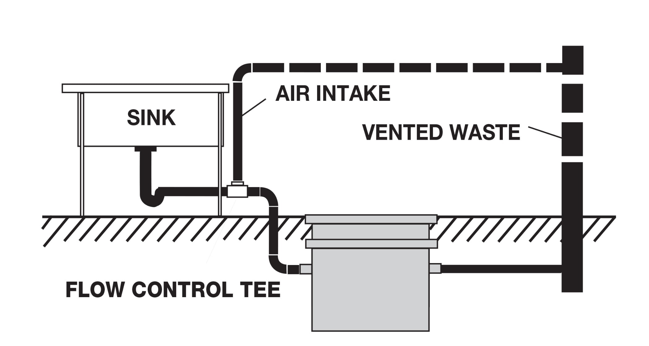
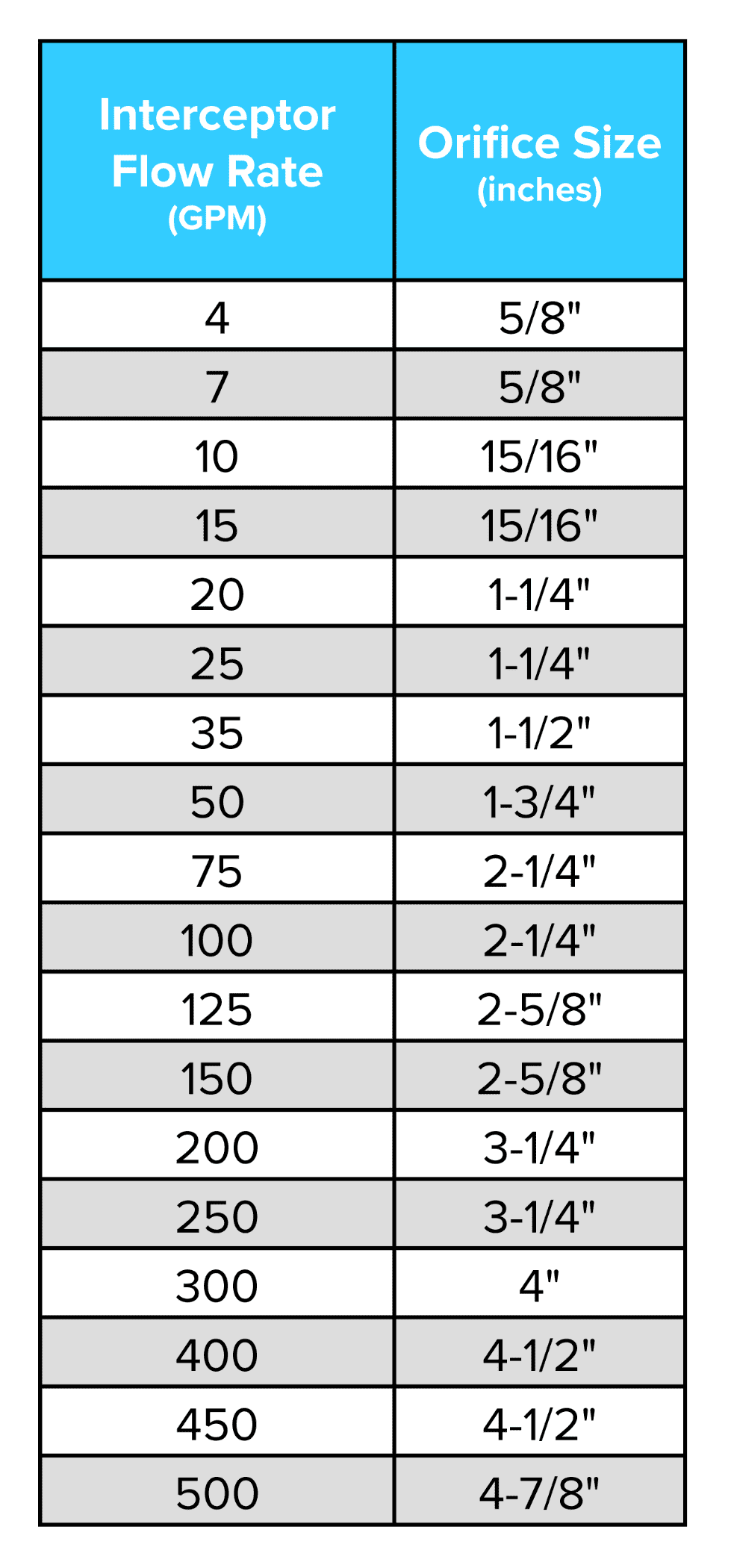
A flow control device is typically designed with an integral orifice (opening) to assure that an interceptor has optimal flow rate, and air intake. The following chart indicates the appropriate orifice size for gravity flow conditions (where no pressure or “head” is present).
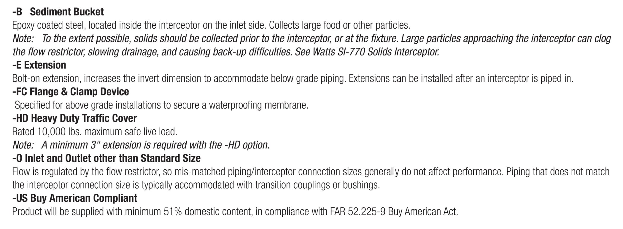
Commonly Specified Options
Maintenance and cleaning
The cleaning frequency of a grease interceptor system is determined by the capacity of an interceptor (measured in pounds of grease that can be trapped within it) and the amount of incoming grease.
Because of this, grease removal intervals may vary from once a week to once every several weeks. When the necessary cleaning schedule has been determined based on a unit’s specific application and size, regular cleaning is necessary to maintain the system’s function and efficiency.
After the removal of accumulated grease and waste material, the interceptor should be thoroughly checked for any clogs or blockages in the inlet, outlet and air relief.
The following steps should be followed during the grease removal and cleaning process:
Loosen and remove any fasteners used to secure the cover;
Remove the cover;
Clean out any grease;
a. If applicable, use a scoop or shovel to remove any remaining solidified grease in unit;If present, remove the sediment bucket; empty and clean thoroughly;
Using a clean water supply, hose down and wipe out the inside of the body;
Check integrity of cover sealing gasket (replace if needed); and
Reinstall cover and lock down hardware.
If there is a semi-automatic interceptor in place, use the following steps for cleaning:
With the outlet valve open, run a full stream of clean hot water (140° F minimum) through the interceptor for at least 2 minutes;
Allow unit to cool for approximately 3 minutes;
Close the valve on the outlet side of the interceptor;
Remove cap from top of interceptor and attach draw-off hose; position hose to drain into waste receptacle;
Run hot water through the interceptor at rate of 1.5 to 2.5 gpm;
Once filled, force the liquified grease out through the top draw-off hose;
When clear water begins to discharge through the draw-off hose, the interceptor is clean;
Disconnect the draw-off hose and replace the pipe cap; and
Re-open the valve on the outlet and your interceptor is ready for normal use.
Robert DiPlacido, is a product manager at Watts Water Technologies.

