Choosing the right balancing valve
Specify the right product for the project.
By Kevin Freidt
Several different balancing valve technologies exist in today’s market; some are new and some have been around for decades. A working knowledge of the entire range of options will serve you well when selecting the correct approach for your specific hydronic or plumbing system project.
Manual balancing valves
Manual (also known as pressure-dependent or static) balancing valves have been the industry workhorses for decades. They are called “static” balancing valves because once they are adjusted, there is no movement of the internal components. Most have two pressure-test ports (PT) for measuring differential pressure across the internal flow restriction, which is then correlated to a flow rate using a graph or chart of some type.
There are two types of manual balancing valves. A fixed orifice (FO) type and a variable orifice (VO) type. Orifice refers to the portion of the valve located between the two PT ports.
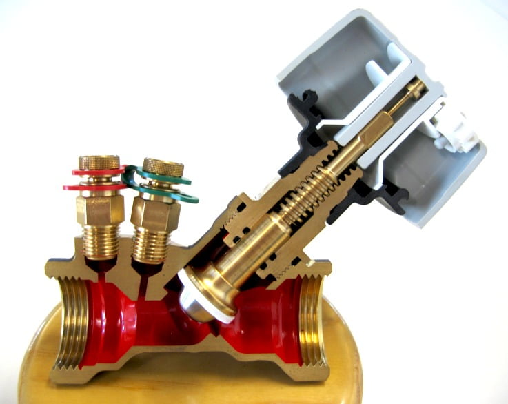
Fixed orifice, 3/4-inch.
Figure 1
Fixed orifice balancing valves
In a FO valve, there is no change in internal geometry between the differential pressure ports; the orifice remains fixed while the valve is being adjusted at a plug and seat adjacent to the orifice.
A direct relationship exists between pressure drop across the ports and the flow rate. That relationship is governed by the following formula:
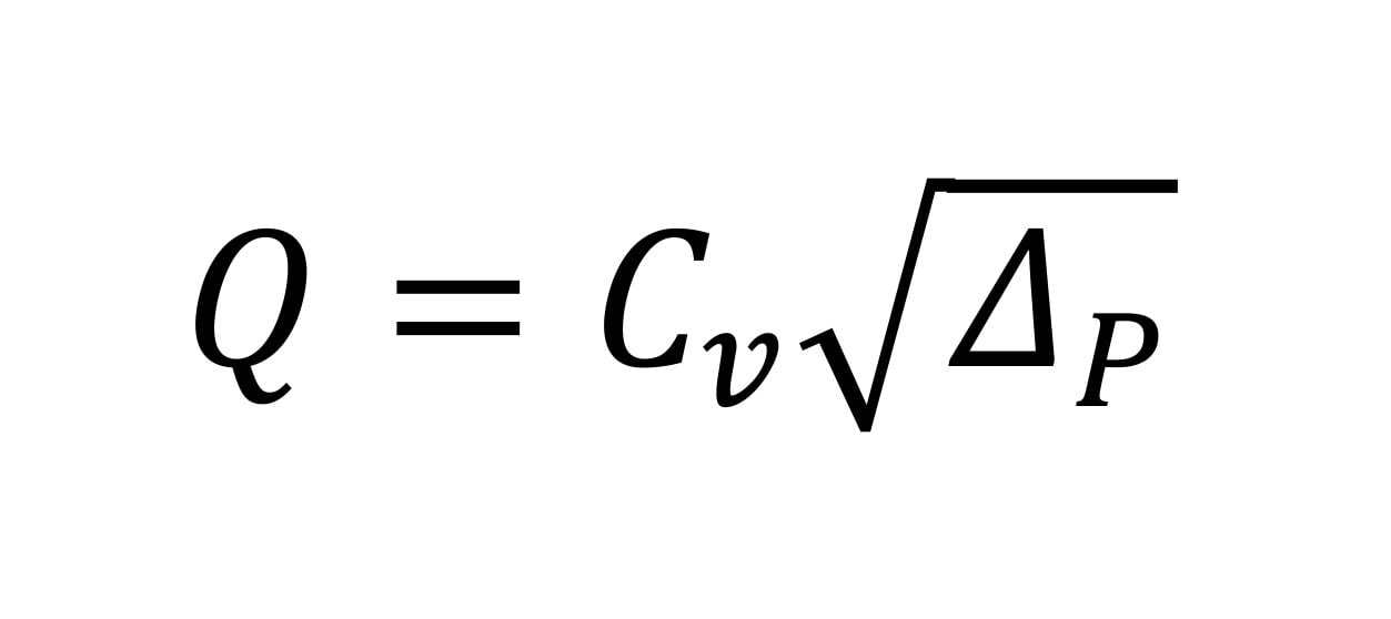
Where:
Q = flow rate (in gpm);
Cᵥ = the flow coefficient of the orifice between the ports; and
ΔP = the pressure drop across the ports (in psi).
For example; the manufacturer’s published Cᵥ value for the valve in Figure 1 is 6.4. If the ΔP across the ports is measured as 0.3 psi, then the calculated flow rate is:
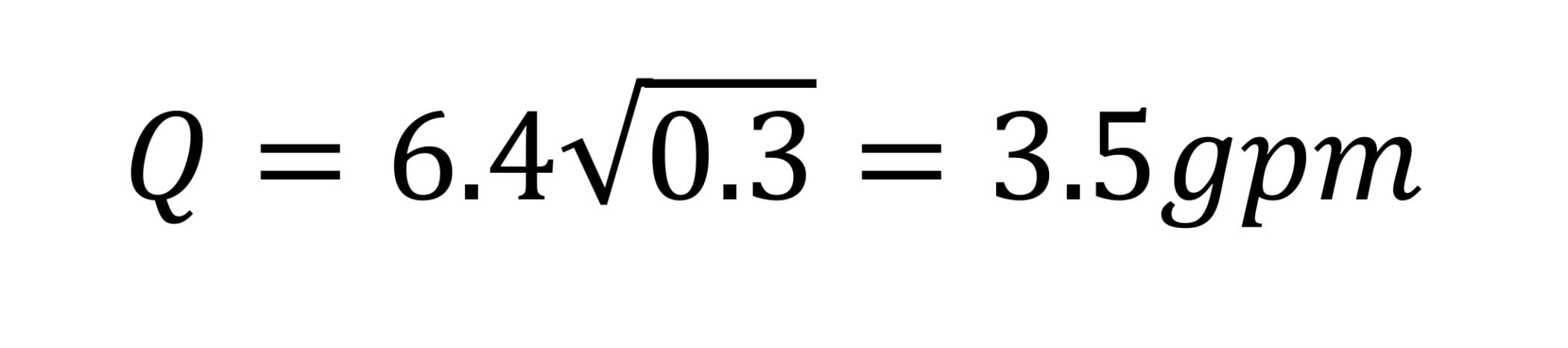
To eliminate the need for installers to do this calculation, manufacturers plot the relationship on wheels or charts to allow quick determination of flow rate. Figure 2 shows a chart for the valve shown in Figure 1. The red lines show how the previously calculated flow is determined.
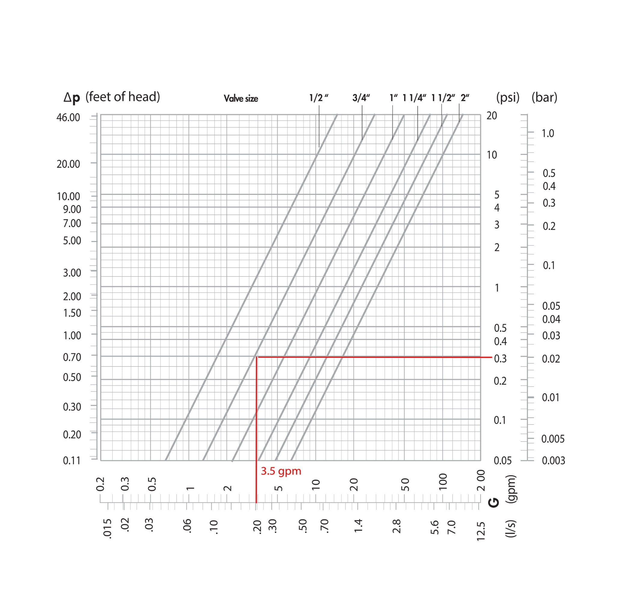
Flow versus pressure drop chart, fixed orifice.
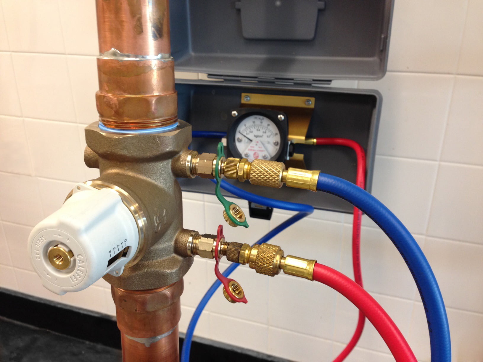
Variable orifice balancing valve with differential pressure tool hook-up.
Figure 2
Figure 3
ENLARGE
Special instruments are used to measure differential pressure across FO and VO balancing valves. Some digital manometers can be programmed to directly convert the differential pressure measured across a valve to a flow rate reading.
Variable orifice balancing valves
Figure 3 shows an example of a variable orifice (VO) valve connected to a differential pressure tool. As the contractor turns the knob to adjust flow, the geometry of the orifice varies because the plug and seat are in between the PT ports.
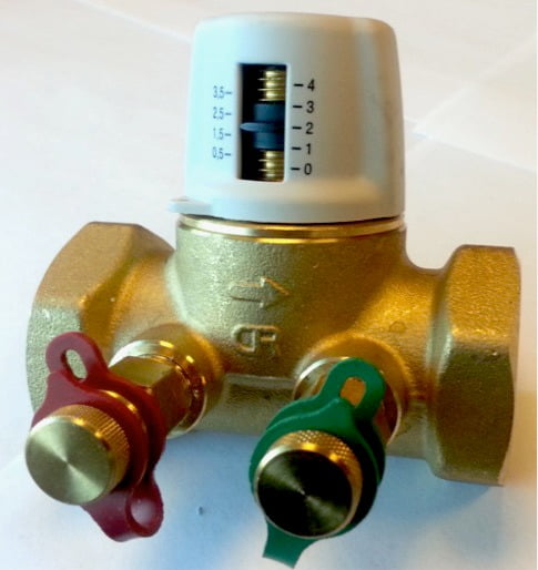
Variable orifice valve with knob set at index 2.
Figure 4
Thus the Cᵥ value of the orifice changes as the valve is adjusted. This makes the procedure for determining flow rate more involved than with a FO valve. Manufacturers publish a family of curves for each size valve. Each curve relates to a specific knob position. Figure 5 shows the family of curves published for the valve shown in Figure 4. The red lines illustrate how a knob setting of 2 combined with a measured differential pressure of 3 psi, indicates a flow rate of 3 gpm.
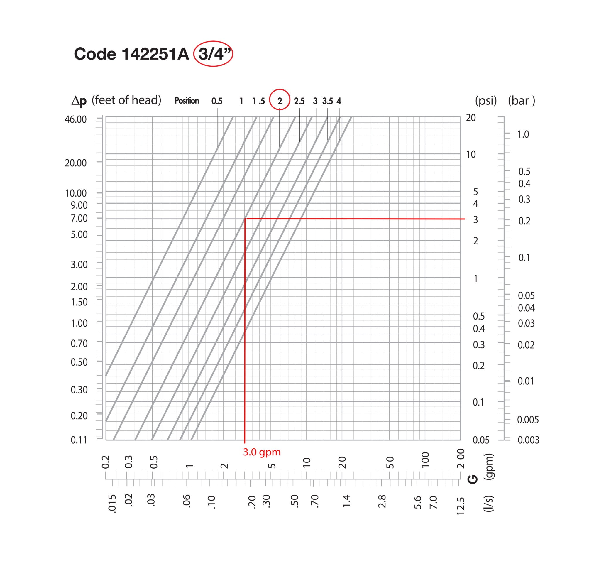
Flow versus pressure drop chart, variable orifice.
Figure 5
ENLARGE
If this flow measurement of 3 gpm was the first one conducted, and 5 gpm is the desired flow rate for the circuit, the contractor might choose to open the valve to position 3 or 4, determine the new flow rate, and through simple interpolation, determine the knob setting that should result in a flow rate close to the target value of 5 gpm. This process would be repeated, as necessary, until the target is attained.
Balancing a circuit with traditional manual balancing valves is an iterative “trial and error” process. Furthermore, because circuits are hydraulically coupled, adjusting flow in one circuit affects flow in the other circuits. A system with 10 circuits can require 50 or more readings and adjustments to achieve the desired flow rates. Accurate balancing requires skill and experience. Various testing, adjusting and balancing (TAB) organizations exist in North America to train and certify balancing professionals.
Direct reading balancing valves
A variation of the FO valve was introduced in North America a few years ago, and doesn’t require ΔP readings. Instead, it uses a built-in flow meter. The flow rate is directly read by the balancing technician. This type of valve is generally more expensive than traditional manual balancing valves, but can simplify balancing, reduce balancing labor time significantly and eliminate errors. Figure 6 shows an example.
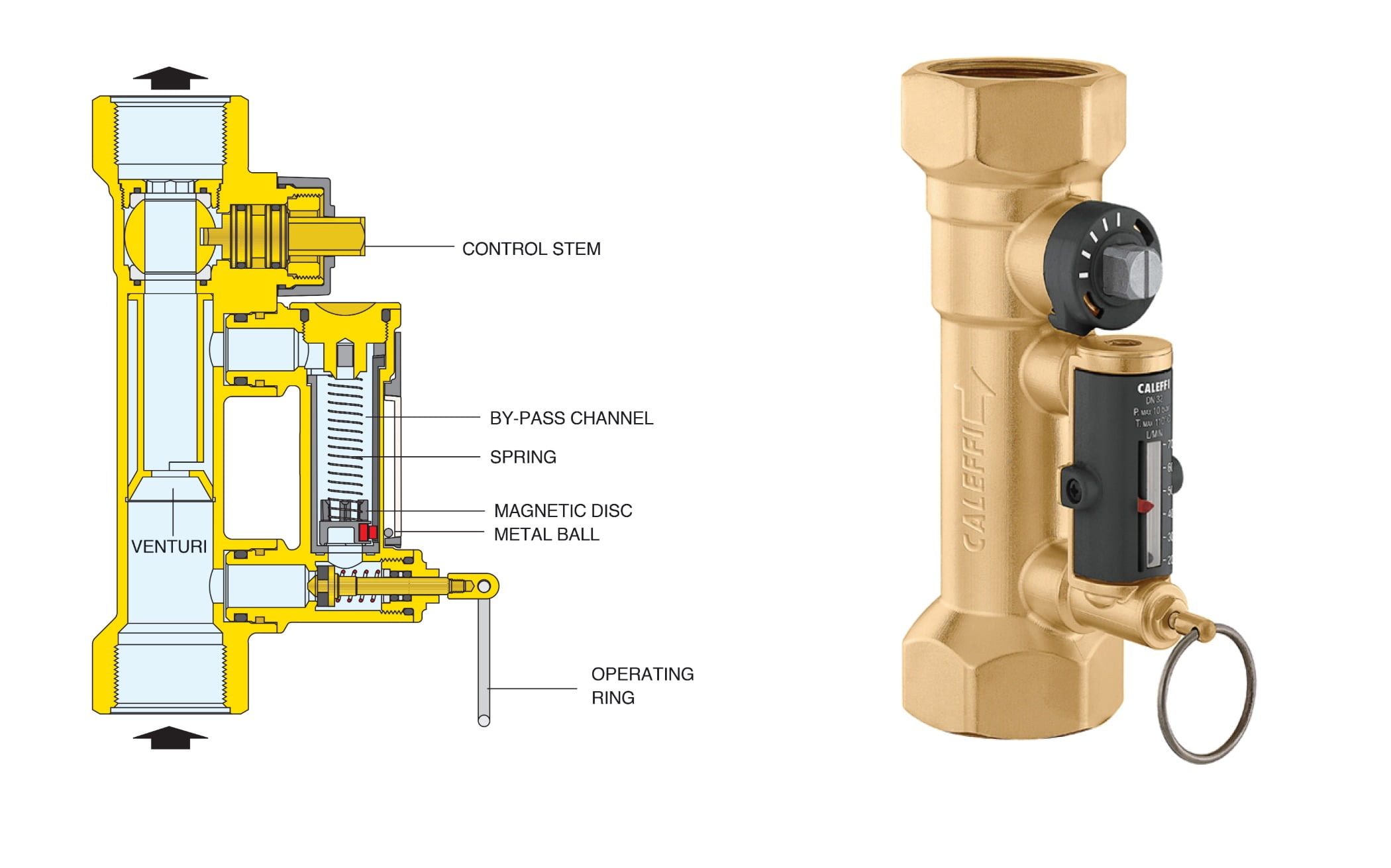
Direct reading manual balancing valve.
Figure 6
This type of valve contains a bypass channel connected to both sides of a fixed venturi. To set the flow rate, the balancing technician pulls the ring on the bypass valve which allows flow through the bypass channel. A spring/disc mechanism travels within this bypass channel a distance that is proportional to the valve’s flow rate. The disc is magnetic and attracts a small steel bead located within an external sealed glass cylinder. The cylinder graduations are calibrated so that the bead location indicates flow rate.
To set the flow, the balancing technician simply rotates the control stem with a wrench while viewing the meter until reaching the target value, then releases the ring. Circuit flow can be set in a fraction of the time required for traditional manual balancing valves. Furthermore, common sources of error — such as incorrectly calibrated instruments, misinterpreting pressure readings, incorrectly interpolating logarithmic charts and incorrectly interpolating adjustment knob positions — can be eliminated.
In low flow rate applications, such as domestic hot water recirculation systems, the calculated branch flow rates required to maintain a minimum temperature at the farthest fixture are frequently so low that they are difficult or impossible to read using traditional manual balancing valves that rely on differential pressure. For a given flow rate, the differential pressure across a VO valve is greater than that of a FO valve, so it is easier to read — seemingly an advantage. But an offsetting factor is having to interpolate based on adjustment knob position.
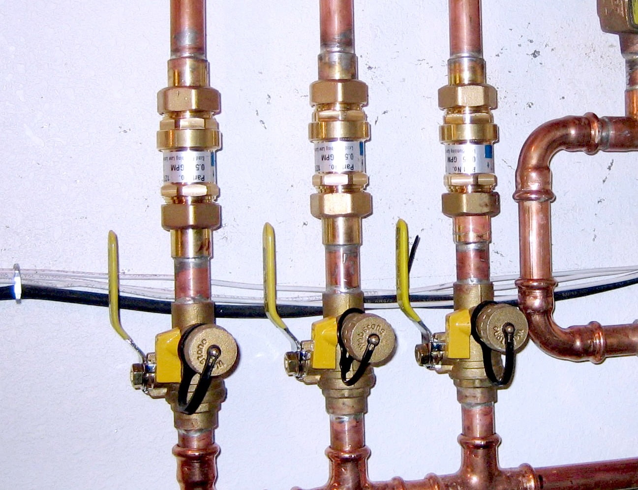
Because of their advantages, direct reading manual balancing valves are gaining popularity for both hydronic and DHW recirculation applications. Figure 7 shows an example of a low lead version on a DHW return riser. Notice the minimum graduation of 1/2 gpm on the scale. This is a commonly specified circuit flow rate, and it would be challenging to achieve using a balancing valve with PT ports.
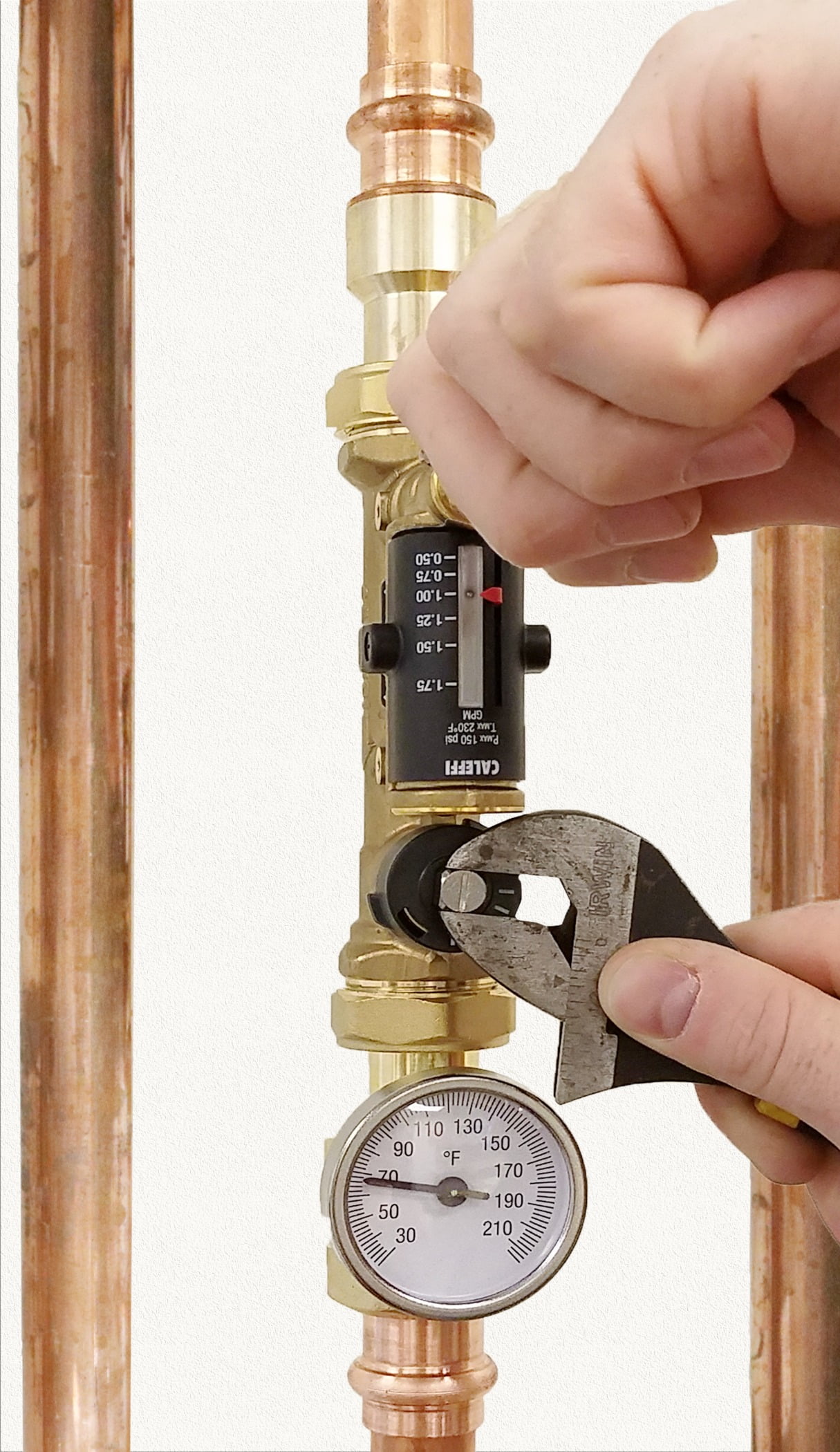
Figure 7
Automatic balancing valves
Figure 8 shows a type of balancing valve type often referred to as an automatic (or pressure independent) balancing valve. Unlike a manual balancing valve, an automatic balancing valve has an internal cartridge that moves to maintain a constant flow rate as differential pressure across the valve varies. These valves are sometimes referred to as “dynamic” balancing valves.
Pressure independent balancing valves.
Figure 8
Other balancing valves technologies now exist that also have moving parts. They include thermal balancing valves and pressure independent control valves. These valves are also automatic, so the simple descriptor of “automatic” is no longer sufficient. We like to refer to the valve type shown in Figure 8 as a “pressure independent” (PI) balancing valve to differentiate it from a thermal balancing valve or pressure independent control valve (PICV).
Unlike a static balancing valve, a PI balancing valve controls flow rate within a circuit to a fixed value based on a “characterized” opening in the cartridge, as shown in Figure 9. As differential pressure across the valve increases from 0 to the minimum value of the working range, flow increases proportionally. Up to this condition, the cartridge within the valve has not yet moved and the spring has not yet begun to compress (as shown in Figure 9a). As differential pressure continues increasing, the cartridge begins compressing against the spring (as shown in Figure 9b), reducing the characterized flow aperture area and keeping flow constant. This regulation process continues as pressure increases to the maximum differential pressure value of the working range. Above the maximum differential, flow rate will then increase because the spring is fully compressed (as shown in Figure 9c). In a multi-branch system, pressure independent valves maintain stable flow rates within each branch.
Because PI valves are supplied with a pre-calibrated flow rate cartridge, they are essentially “plug-and-play,” and require no balancing labor. Several designers prefer PI valves over manual valves to simplify commissioning. They are effective in both hydronic and plumbing (low lead models) applications.
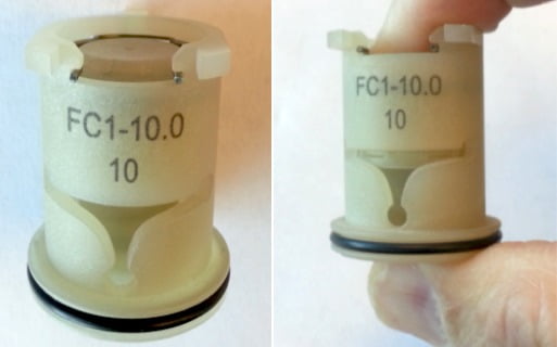
Characterized cartridge assembly for 10 gpm.
Figure 9
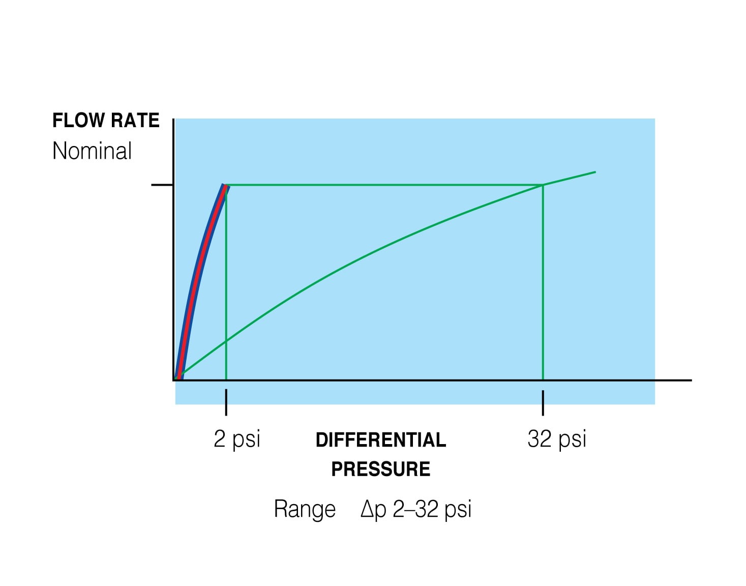
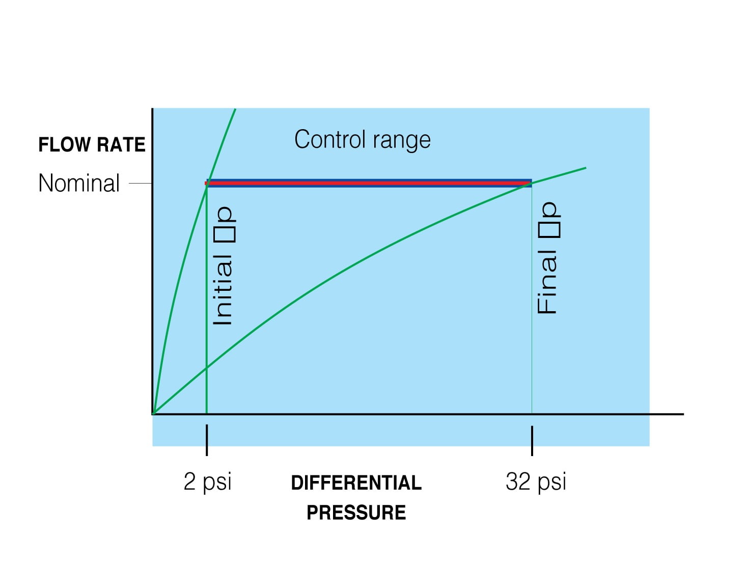
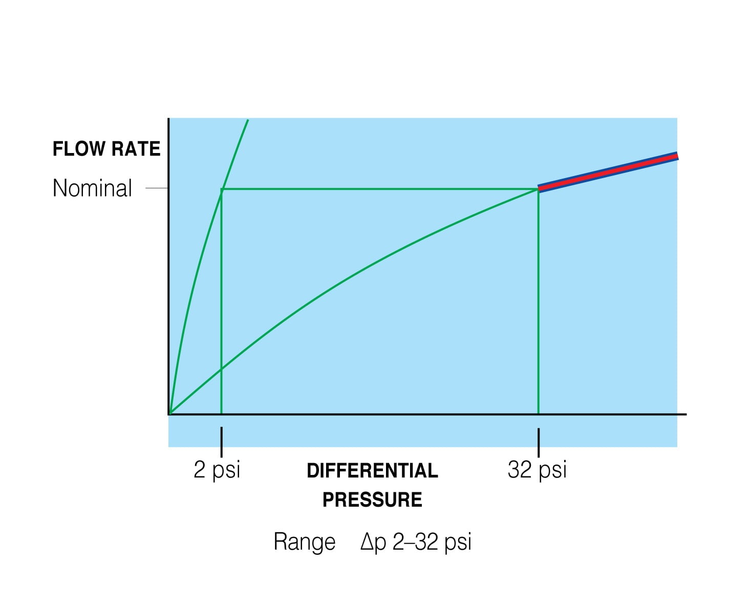
Figure 9a
Figure 9b
Figure 9c
ENLARGE
ENLARGE
ENLARGE
Thermal balancing valves
A relatively new type of balancing valve is the thermal balancing valve (TBV). It is designed primarily for balancing domestic hot water recirculation circuits. A TBV modulates flow rate within a circuit to maintain a fixed temperature. In recirculating domestic hot water systems, this is significant because unlike hydronic applications where balancing is intended to control heat transfer, in recirculating DHW systems balancing is done to ensure adequate water temperature at the fixtures. The water entering the valve is coming from the DHW hot water supply line, so increasing the flow increases the temperature at the valve. TBVs are a temperature solution for a temperature problem.
Some TBV models are available with a bypass feature that allows the thermal balancing valve to be used in a thermal disinfection application for control of Legionella.
Both fixed temperature (non-adjustable) and field adjustable TBV types are available. Figure 10 shows a contractor adjusting a field adjustable type TBV within a circuit return riser.
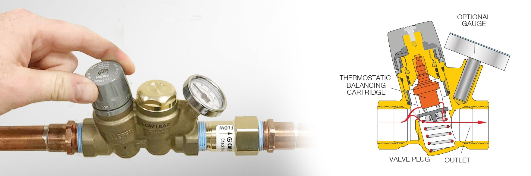
Field adjustable thermal balancing valve.
Figure 10
In a TBV, an internal thermostatic balancing cartridge expands and contracts in response to water temperature passing through the valve. When cool water is present, the valve plug is fully open to maximize flow. As water temperature rises, the valve begins to close down until the temperature reaches the user-set value. At and above set point temperature, the valve plug is at minimum position, open just enough for ongoing temperature sensing.
This modulating action of the TBV ensures automatic water temperature control within each recirculating branch. When combined with a variable speed circulator, operating in constant pressure mode, TBVs can result in energy savings because when the system temperatures are at set point and the valves are at minimum position, the circulator will slow down and reduce energy consumption.
In summary
Due to their history and familiarity, manual balancing valves are still the go-to valve for many industry professionals. Automatic valves eliminate the balancing labor associated with manual valves, and are a good choice if constant gpm is the designer’s primary goal.
For domestic hot water circuit temperature control, thermal balancing valves are hard to beat due to their simple no-balancing, temperature-based technology. There are more choices than ever before in balancing valves; with just a little information, you can make the right choice for your balancing project.
Kevin Freidt, LEED AP, is the director product management and technical support at Caleffi North America. Freidt has a bachelor's degree in mechanical engineering technology, more than 30 years of experience in the commercial HVAC industry and is a member of ASPE.

scroll down for more
Scroll down for more content
NEW
PRODUCTS
TECHTOPIC