

Rekindled interest
Soaring fuel costs drive adoption of high-efficiency/low emissions wood-burning boilers.
RENEWABLE HEATING DESIGN || By John Siegenthaler, P.E.
RENEWABLE HEATING DESIGN
|| By John Siegenthaler, P.E.
RENEWABLE HEATING DESIGN || By John Siegenthaler, P.E.
In 2012 the price of #2 fuel oil in upstate New York was approaching a previously unheard of $4 per gallon. This spurred many pending heating system projects to consider the use of cordwood or wood pellets.
NYSERDA (New York State Energy Research & Development Authority) committed several million dollars to a program to promote high-efficiency/low emissions (e.g., HELE) wood-burning boilers (eg. cordwood gasification boilers with storage, and pellet-fuel boilers).
That program, called Renewable Heat NY, remained in place through mid-2021. Several boiler suppliers went through the process of getting their boilers on NYSERDA’s “qualified technology” list. Several hundred contractors and engineers went through training programs to learn the nuances of merging these boilers with hydronic heating distribution systems — both existing and new.
Many lessons were learned over the years this program ran. Some of the key takeaways were:
- It makes no sense to use a cordwood gasification or pellet-fired boiler without adequate thermal storage. Doing so forces the boiler to operate with short cycles and at significantly lower efficiency and higher particulate emissions. A guideline for cordwood gasification boilers was 130 gallons of water storage per cubic foot of volume in the boiler’s primary combustion chamber. For pellet-fired boilers, the guideline was a minimum of 2 gallons of water storage per 1,000 Btu/h of boiler output rating;
- All wood-fired boilers need protection against sustained flue gas condensation by maintaining the boiler inlet temperature above 130° F (minimum) whenever possible;
- The lower the water temperature at which the heating distribution system could operate, and still maintain comfort in the building, the better the seasonal efficiency and the lower the total particulate emissions of the biomass boiler;
- The barometric dampers used on solid-fuel boilers with draft inducting blowers need to seal against positive pressure in the vent connector piping. Without this sealing ability, the dampers allow gaseous and visible soot emissions to temporarily escape from the venting system into the building due to a combination of minimal draft from a cold chimney and pressure created by an inducer fan within the boiler;
- A low thermal mass UL103-listed double wall insulated chimney, routed upward through the building, could establish proper draft much faster than an exterior masonry chimney;
- It’s necessary to prevent heat generated by an auxiliary boiler from being inadvertently routed through the thermal storage tank; and
- The closed-loop system will require an expansion tank having a volume of approximately 10% that of the thermal storage tank.
Here we go — again
Fast forward to the end of 2022. That $4 per gallon price for #2 fuel oil would be a “steal” in the market as this is being written. The average price in upstate New York in late fall was $5.78 per gallon, and it’s upwards of $6 per gallon in downstate.
These dramatic price shocks have definitely renewed interest in wood burning. Pellet stoves are selling well, and so are modern low-emission wood stoves. Both are benefiting from 26% federal income tax credit incentives that remain in place through 2022.
Interest in wood-burning boilers is rising, but the higher installation cost and complexity of such systems remain a significant obstacle to widespread adoption. Compounding the issue are uncertainties about how federal legislation, such as the Inflation Reduction Act, may apply to high-efficiency/low-emission wood-fired boiler systems beginning in 2023.
Realization vs. aspiration
One thing is for certain. Regardless of any incentives available, if a system built around a HELE wood-fired boiler isn’t done right, the clients who’ve laid out substantial capital are not going to be happy with the results. To that end, Figure 1 shows a “starting point” for a system design.
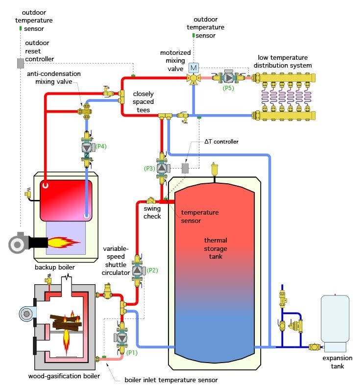
Figure 1
ENLARGE
The best way to understand this “starting point” layout is to break it up into subsystems. Let’s start with the “biomass subsystem” as broken out in Figure 2.
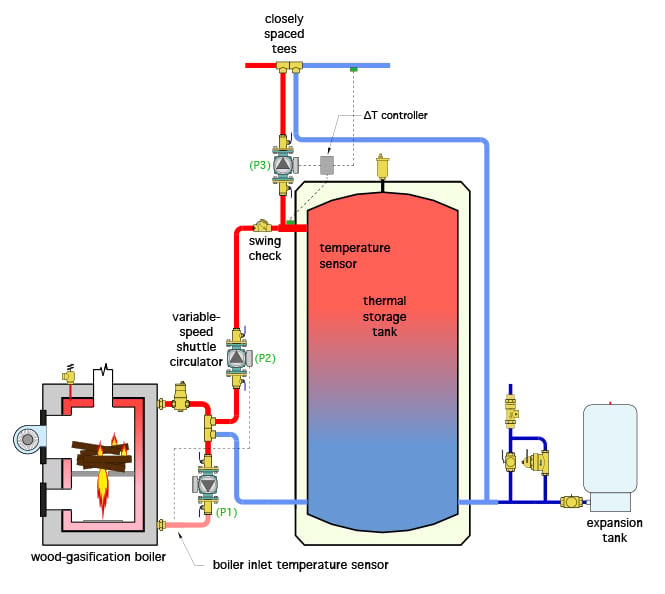
Figure 2
ENLARGE
All biomass boilers require protection from sustained flue gas condensation. There are several ways to do this. In this system, it’s done using a variable speed “setpoint” circulator (P2). Circulator (P1) runs at a constant speed whenever the wood gasification boiler is operating. Circulator (P2) monitors the boiler inlet temperature, and starts moving water when that temperature rises above some setpoint (typically about 130° F). It reaches full speed when the boiler inlet temperature reaches about 135° F or higher. This action provides a “thermal clutch” between the boiler and tank or the load. It allows mixing to occur at the lower tee to boost boiler inlet temperature as needed to prevent sustained flue gas condensation. A pair of closely spaced tees provide hydraulic separation between circulators (P1) and (P2).
Heated water from the biomass boiler can go into the thermal storage tank, or, if the space heating load is active, be routed to the distribution system by circulator (P3). In the latter case there’s a unique control concept involved. Circulator (P3) is only allowed to operate when the temperature at the upper tank header is at least 3° F above the water temperature at the return side of the distribution system. This logic is necessary to prevent the inadvertent transfer of heat, generated by the backup boiler, from entering the thermal storage tank. It’s easy to accomplish with a simple differential temperature controller or equivalent BAS programming.
All heat from the biomass subsystem is injected into the distribution system at a pair of closely spaced tees. These tees provide hydraulic separation between circulator (P3) and the distribution circulator.
The swing check valve at the upper tank header prevents reverse thermosiphon flow from the tank through the wood-fired boiler when it’s inactive. It also allows forward thermosiphon flow between the boiler and tank if a power outage occurs when the boiler is operating. Some cordwood gasification boiler manufacturers may also require a passive heat dump mechanism in lieu of the piping details shown in Figures 1 and 2.
Backup subsystem
Most systems with biomass boilers also have a backup boiler. In many cases, it’s an existing boiler that’s repurposed from the building’s sole heat source to a new role as a backup heat source. It’s there to maintain comfort in the building if the biomass boiler is not operating. A typical example is when a cordwood gasification boiler is not being fired because the building occupants are away.
Figure 3 breaks out the piping for a backup boiler. The assumption is that it’s a conventional boiler, and as such, requires protection from sustained flue gas condensation when paired with a low-temperature distribution system.
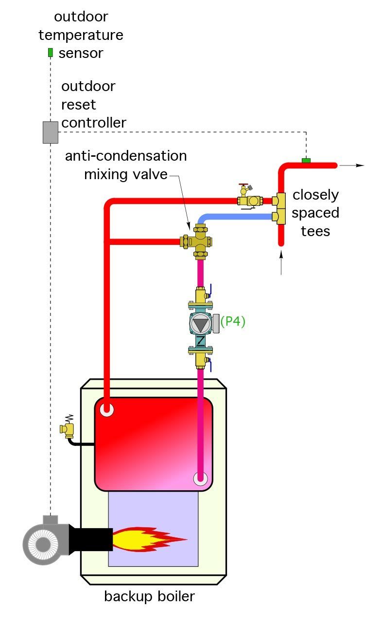
Figure 3
ENLARGE
The closely spaced tees for this subsystem are located “downstream" from those that connect the biomass subsystem. Doing so allows the latter to contribute heat to the water returning from the load at the lowest possible temperature, and thus helps widen the potential temperature cycling range of the thermal storage tank.
Also note that an “anti-condensation” valve has been added to the backup boiler system. This high-flow capacity thermostatically-regulated mixing valve is there to boost the boiler inlet temperature above the dewpoint of its flue gases whenever possible.
A simple outdoor reset controller monitors the water temperature supplied to the distribution system whenever there is a call for space heating. If that temperature falls slightly below the minimum target supply water temperature to the heat emitters, the backup boiler and its associated circulator are turned on. This helps ensure that heated water at an appropriate temperature will be available to the heat emitters, regardless of the status of the cordwood gasification boiler. Another pair of closely-spaced tees allow the backup boiler to remain “offline” when it’s not being fired.
Final arbiter
The motorized 3-way mixing valve controls the supply water temperature to the heat emitters. That temperature could be based on a setpoint or on outdoor reset control. The mixing valve can accommodate a wide range of hot water temperatures from the heat sources, especially from the biomass subsystem, and ensure that the water temperature reaching the heat emitters is where it needs to be.
As the price of fossil fuel energy continues to rise there’s sure to be increased interest in properly combining the comfort and energy efficiency of hydronic heating with carbon-neutral fuels such a cordwood, pellets and wood chips. The concepts presented above provide a starting point for systems that will use this combination. As with any system, piping, circulators, valves and other hardware all have to be sized and selected for their respective operating requirements. Properly designed, installed and maintained hydronic systems using biomass boilers should provide decades of reliable and efficient service.
ThinkNeo/DigitalVision Vectors via Getty Images.
John Siegenthaler, P.E., is a consulting engineer and principal of Appropriate Designs, in Holland Patent, New York. In partnership with HeatSpring, he has developed several online courses that provide in-depth design-level training in modern hydronic systems, air-to-water heat pumps and biomass boiler systems. The fourth edition of his textbook — “Modern Hydronic Heating & Cooling” — was released in April. For more information, visit www.hydronicpros.com.
