
Squeaky wheel gets the grease
Understanding friction concepts.
WATER COOLER CONVERSATION || By Ethan Grossman, P.E., CPD
WATER COOLER CONVERSATIONS || By Ethan Grossman, P.E., CPD
WATER COOLER CONVERSATIONS
|| By Ethan Grossman, P.E., CPD
[DevidDO]/[iStock/Getty Images Plus] via Getty Images.
Friction is everywhere. Even though friction finds itself in just about every system we design, it is one of those concepts that is not easily understood. Why do some designs accomplish the transfer of material and energy the way we expect them to while other designs fall short? At home, a drop of oil on a squeaky hinge could help a door close more smoothly. In piping and duct designs, understanding how the system will operate and choosing the right size pipe or duct will assure the correct amount of fluid is delivered at the correct pressure.
I like to visualize friction loss as rush hour traffic on a busy highway or the packed shuffling of a crowd leaving sports and concert venues. There are only so many cars you can pack on a highway, and only so many people you can get through a coliseum corridor (otherwise known as “egress” in architectural circles). Think back to our flow formula, Q=VA. For the two real life examples above, the area A is constant. As the vehicular or foot traffic slows down, so does the overall flow rate.
Plumbing application
A good example of friction loss in plumbing design is a hot water recirculation system. Hot water recirculation utilizes a pump to keep hot water circulating through a piping network to make up for heat loss. The first step in sizing any system that uses a pump is to plot a system curve.
In order to plot a system curve, I imagine how much pressure the pump will need to overcome at a variety of flow rates. I’d suggest keeping it simple and picking four points. Say, for example, 0%, 25%, 50% and 100% flow.
Let’s say our hot water piping network is a straightforward design, with 100 feet of 1” pipe that telescopes down to 75 feet of 3/4-inch pipe and 50 feet of 1/2-inch pipe. One simple loop that could take care of a group of public restrooms or dwelling units. I have a spreadsheet already set up that calculates the amount of heat loss through piping, and it shows me there would be around 4,000 Btu/h of heat loss through the pipe network.
You may remember that 1 Btu is defined as the amount of heat required to raise 1 pound of water 1° F in 1 hour. This helps understand the Btu a little more intuitively, but takes practice converting water flow from gallons per minute to pounds per hour. I’d encourage you to take out a pencil and scratch pad to practice.
Speaking of gallons per minute, exactly how much flow do we need to overcome that 4,000 Btu/h of heat loss? This is where we sometimes here the question: “What is the acceptable ΔT?” In other words, “How low can we allow the temperature to drop before we turn on the recirc pump and bring the system back up to temp?” Referring to the ASPE Plumbing Engineering Design Handbook, Volume 2, we can use the following formula:
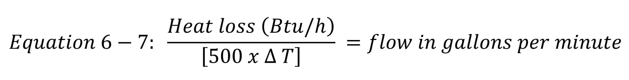
For our example of a simple recirculation system above, the required flow rate at a 10° ΔT would be:
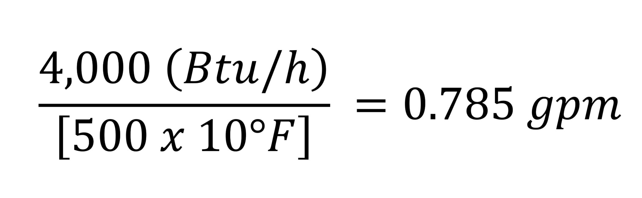
This is the part that might surprise you. The amount of flow required to account for heat loss isn’t actually as much as we might expect. We rarely size pumps for such low flow. Some thermostatic mixing valves require a minimum flow of up to 8 gpm just to be effective. This is where the system curve becomes important. At 0.785 gpm, our pipe network would have a friction loss of or around 1.6 feet of head. At 8 gpm, the friction loss jumps up to 88 feet of head. That’s 38 psi in friction loss alone.
For a quick sanity check, and to plot a system curve, I like to use a book called “Cameron Hydraulic Data.” I picked up a used copy once from 1965 and refer to it frequently. Referring to the table for 1/2 inch type L copper, I can see that 8 gpm will exhibit a friction loss of 116 feet per 100 feet of run. I’d recommend keeping a copy of the book, or a similar reference, at your fingertips.
A lot of us would probably be inclined to upsize our recirculation pump. That might not be a good idea to overcome friction loss if your pump has a flat curve and “deadheads” at a low pressure anyhow — kind of like trying to cram more cars onto that highway. Eventually the traffic comes to a standstill.
Friction can be an in-depth topic unto itself. Thankfully for plumbing and HVAC engineers, the friction analysis for the machinery we specify is taken into account by the engineers who design the bearings, seals, shafts and motors. A good portion of this falls under the category of Coulomb friction. Plumbing and HVAC engineers are primarily concerned with Fluid friction, as the above example shows.
Imagine yourself inside a mechanical room. If the room was designed before VFDs became cost effective, you might hear the sound of belt driven machinery, with sheaves turning on shafts supported by bearings in pillow blocks. If you look closely, you can see grease fittings tapped into the cast body of the blocks, designed so maintenance personnel can grease the bearings and keep everything humming along. If you listen close, you might hear the turbulent flow of water flowing through pipes. Noise in pipes can be reduced by sizing the pipe correctly at an acceptable flow velocity.
As far as squeaky sheaves, that maintenance staff is going to do the best they can to give that wheel the grease, keeping in mind that there is only so much grease you can add before they lose their bearings and need to be replaced.
Ethan Grossman, P.E., CPD, is the plumbing and fire protection discipline leader at Smith Group’s Boston office. He can be reached by email at ethan.grossman@smithgroup.com.

scroll down for more
Scroll down for more content
NEW
PRODUCTS
TECHTOPIC